The ePaper driver board features a 24-pin FPC connector, built-in charging IC for efficient and safe battery charging, and a JST 2-pin BAT connector for easy battery connection. Ideal for creating WiFi-enabled digital photo frames.
2 Likes
Hello - I have both the v1 and, now, the v2 of the ePaper Driver Board. The example code running on an ESP32C6 XIAO runs on the V1 board, but when I transfer the XIAO and ePaper display (1.54") to the V2 board, it displays scattered dots on the screen. Transfer it back to the V1 board and it is fine. Are the two board variants not drop-in replacements? What code do I need to change to adapt to the V2 board? Thank you!
1 Like
Hi there,
and Welcome here…
So I don’t believe they are the PINS are different I believe for both demos, Check the WIki and compare they are next to each other so should be easy to figure out, The 2.0 is pretty robust the 1.5 was a tad on week side. ![]()
HTH
GL ![]() PJ
PJ ![]()
Thank you PJ. I read the wiki thoroughly and don’t see any indication of pin changes as you say. Can you share a picture of the v2 driver board driving a Epaper display successfully? I have 5 pcs of the v2 board and none of them work while the v1 board works flawlessly. Thank you!
interesting… thanks for reporting this bug… can you paste the code here
what XIAO are you using… What program Arduino IDE?
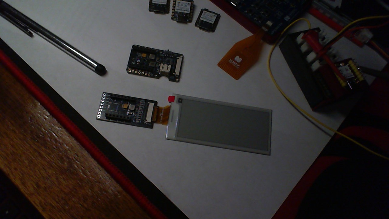
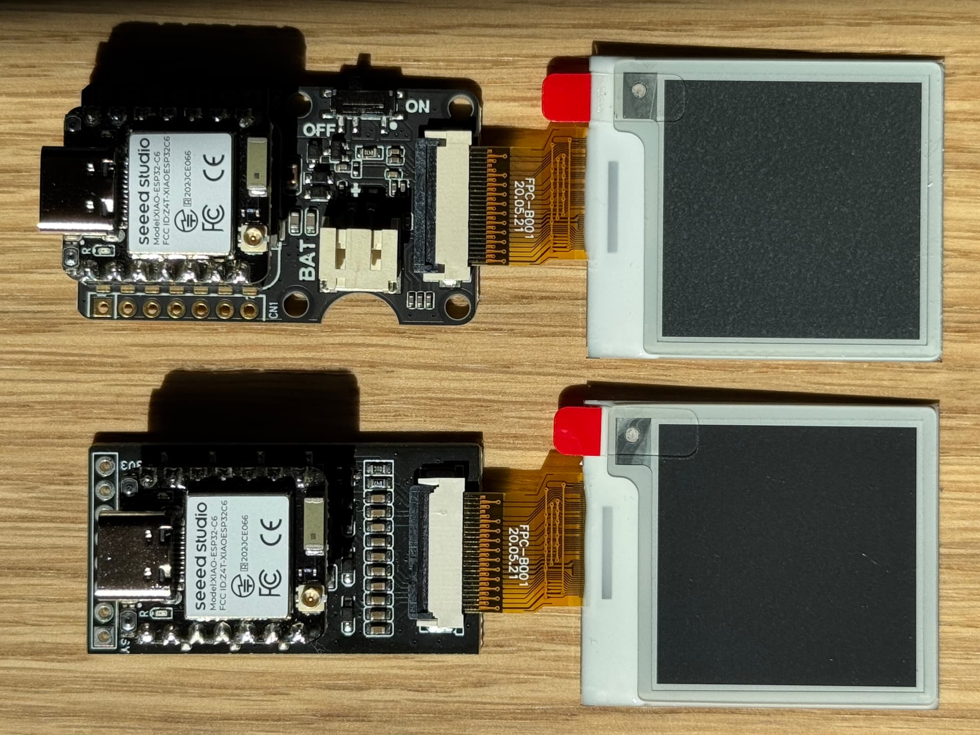
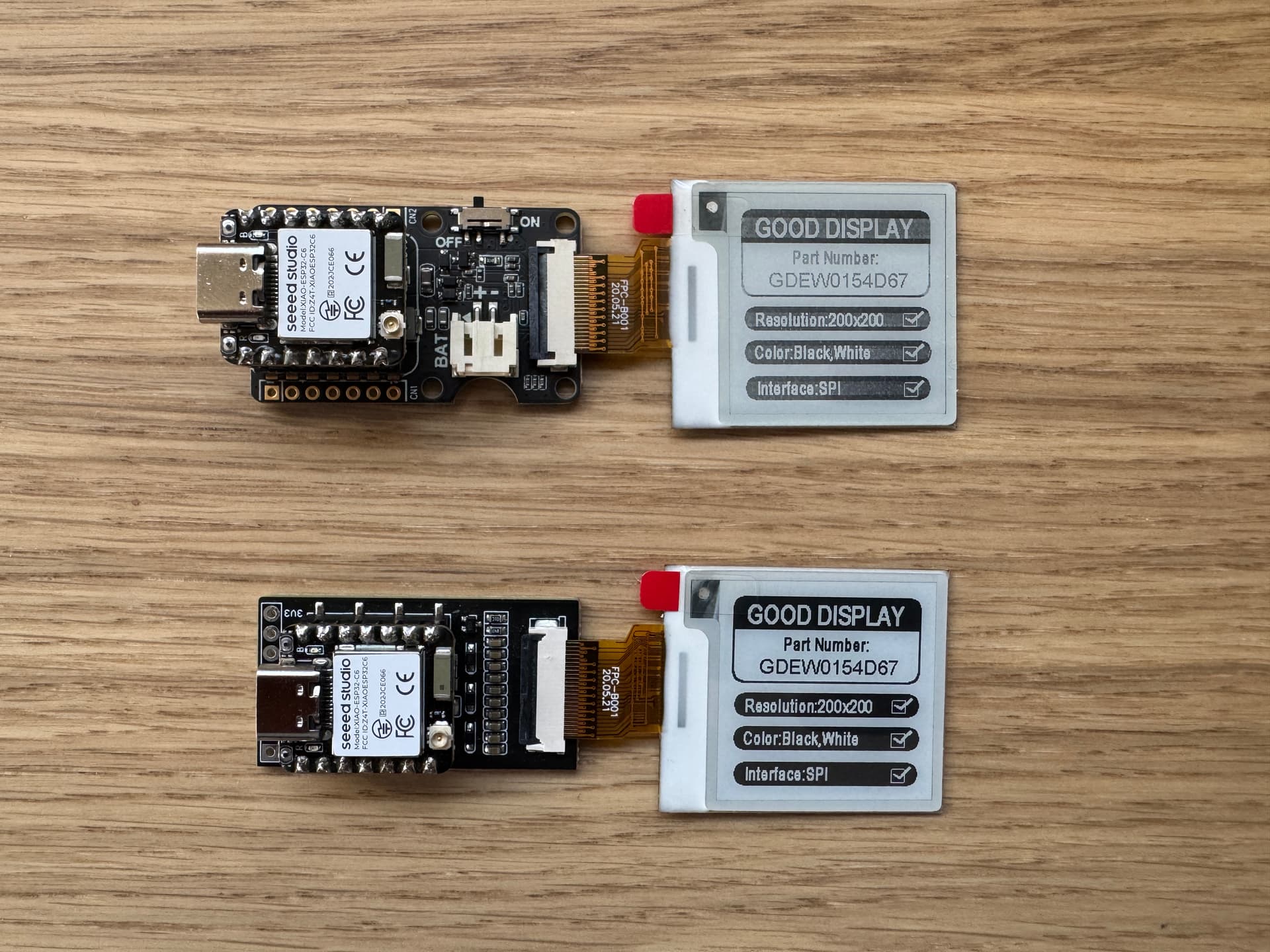
- The display is the
GDEY0154D67(SKU 104990843) - The XIAO is an
ESP32C6(SKU 113991254) - The V1 board (which works) is called the
ePaper Breakout Board(SKU 105990172) - The V2 board (does not work) is called the
ePaper Driver Board(SKU 114993558) - The code is unmodified from the example posted on the Wiki authored by Allen Kuang at GitHub under path
e-ink_Demo / 1.54-inch E-paper - dotmatix 200x200 / example. The same example is linked for both variants of the board. - The Arduino version is 2.3.4 with CLI Version: 1.1.1
I am not allowed to post links or photos, it seems. But if someone can show me how to, I can upload two photos:
- First of the V1 board + ESP32C6 XIAO + 1.54" Display successfully showing the seeedstudio logo and 1.54" display specs on the screen
- Second of the XIAO and 1.54" Display transferred to the V2 board, but showing garbled pixels.
The unmodified code is as below:
#include <SPI.h>
//EPD
#include "Display_EPD_W21_spi.h"
#include "Display_EPD_W21.h"
#include "demo.h"

void setup() {
   pinMode(D5, INPUT);  //BUSY
   pinMode(D0, OUTPUT); //RES
   pinMode(D3, OUTPUT); //DC
   pinMode(D1, OUTPUT); //CS
   //SPI
   SPI.beginTransaction(SPISettings(10000000, MSBFIRST, SPI_MODE0));
   SPI.begin ();
}

//Tips//
/*
1.Flickering is normal when EPD is performing a full screen update to clear ghosting from the previous image so to ensure better clarity and legibility for the new image.
2.There will be no flicker when EPD performs a partial refresh.
3.Please make sue that EPD enters sleep mode when refresh is completed and always leave the sleep mode command. Otherwise, this may result in a reduced lifespan of EPD.
4.Please refrain from inserting EPD to the FPC socket or unplugging it when the MCU is being powered to prevent potential damage.)
5.Re-initialization is required for every full screen update.
7.When porting the program, set the BUSY pin to input mode and other pins to output mode.
*/
void loop() {

      EPD_HW_Init(); //Full screen refresh initialization.
      EPD_WhiteScreen_White(); //Clear screen function.
      EPD_DeepSleep(); //Enter the sleep mode and please do not delete it, otherwise it will reduce the lifespan of the screen.
      delay(2000); //Delay for 2s.
     /************Full display(2s)*******************/
      EPD_HW_Init(); //Full screen refresh initialization.
      EPD_WhiteScreen_ALL(gImage_1); //To Display one image using full screen refresh.
      EPD_DeepSleep(); //Enter the sleep mode and please do not delete it, otherwise it will reduce the lifespan of the screen.
      delay(2000); //Delay for 2s.

      delay(300000);  // The program stops here
}


//////////////////////////////////END//////////////////////////////////////////////////
1 Like
OK, I have figured it out. The SPI bus speed in the example code is too high for the V2 variant of the board for some reason. If I lower it by 100x (100000 instead of the 10000000 in Mr. Kuang’s code) it works on the V2 board as well. Please share with the example author and the R&D team for this board.
1 Like
Hi there,
Good job and eye on getting it sorted and Yes, I found the V2 I had been sent a month ago, Here they are I see they should be pin to pin compatible I think the GPIO’s I was thinking may be just because the Example is a C3. I’ll plug them in and see what’s what.
I had a example or demo on here i think as well, under epaper or eink?
Glad you got it going though the SPI frequency is odd that it’s different. but need to look to the details. ![]()
Please mark YOUR post as the solution so others may find it. It’s a great example of reaching out and solving your own issue by just chopping it up about the issue. Great Stuff!
![]()
GL ![]() PJ
PJ ![]()
2 Likes
I’m afraid my discovery was shortsighted. After 6 hours of debugging with another SW engineer, we found:
-
While the V2 board is able to display “something” with a slower SPI clock, the image is not robust. It is patchy. When rendering a full black screen, it looks black on the V1 board, but like static noise on the V2. I still cannot attach photos, else I could share an image. Swapping the displays between the boards results in the same outcome, so it is not a faulty display.
-
The V2 board will display nothing when the SPI frequency is set to below 20,000 or above 200,000 (approximately), both of which are well below the example-set speed of 10,000,000.
Since all 6 V2 boards in my possession behave the same way, this appears to be a hardware issue with the V2 board. How can this be investigated and resolved?
1 Like
Hi there,
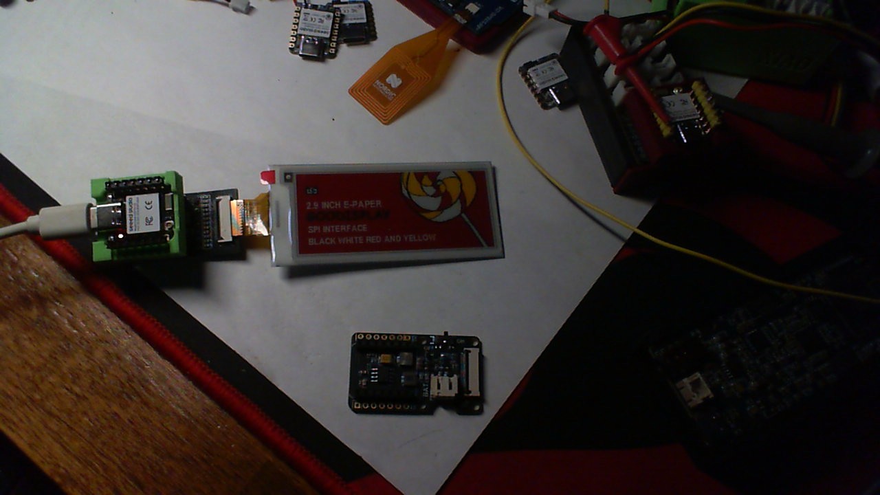
So I have them both and the 2.9" quad color. I found the same below a certain freq it’s lighter. I think it’s the LIB standby and let Seeed Investigate. I’m going to look at it and post some side by side pic’s see if we can shake the tree of knowledge ![]()
Pretty sure there are other adjustments they can make with the LIB Have you tried any other BSP’s for the C6, Do you know which is used in the example you are using? LMK, P
HTH
GL ![]() PJ
PJ ![]()
Wait that is NOT a seeed Display? is it?
Hi there,
So I see on the manufacture of the GOOD Display you are using has their own SPI.h, Have you used their demo examples?
EDIT, no maybe Not…testing it now…
GL ![]() PJ
PJ ![]()
That is, indeed, a Seeed display - SKU 104990843. On the Seeed page for that SKU there is an example listed, which is identical to the one listed on the ePaper Driver Board wiki except for:
- The Driver Board example pin definitions are updated for the XIAO D# scheme
- The Good Display version uses a 100,000 SPI bus
- The Good Display version shows a different test image
The Good Data example’s test image still renders with the same artifacts on the V2 board.
1 Like
Seems like my trust level was just upgraded! ![]()
Attached are the appropriate images showing V1 vs V2 board performance.
2 Likes
Hi there,
Indeed… LOL
Looks to be the case for sure.
Not for any reason but which BSP is being used with these demo’s the current one? 3.1.1 and did you try 3.0.7 ?
asking for a friend… ![]()
![]()
Welcome to the next level … ![]()
GL ![]() PJ
PJ ![]()
Thank you! I installed 3.0.7 and the issue remains the same. I upgraded back to 3.1.3 - no difference.
Looking forward to what Seeed responds with!
trust him… Seeed ant going to go against the great Monkeyface… Even Sharkface doesnt do that…
Hi there,
yes, confirmed… Something is afoot? trying an S3 and C3 next.
Original looks Rock Solid
Pffft … @cgwaltney you give me too much credit. They do All the heavy lifting I just keep an ![]() on them… They work hard behind the scenes too!
on them… They work hard behind the scenes too! ![]()
GL ![]() PJ
PJ ![]()
Where could I find the schematics of the ePaper Driver Board?
Thank you!
1 Like
Hi there,
Yes , Same Question ? Where ? is it?
Definitely not the same as the old one.
Seeed?
GL ![]() PJ
PJ ![]()
I wanted to close the loop here. Seeed sent me revised boards and I’m happy to report that the issue has been resolved; The new boards display nice, deep blacks now.
Seeed Studio ePaper Driver Board (V2)
Part number: 114993558
Old, faulty batch:
MOA250113001
Prod date: 1/20/25
New, fixed batch:
MOA250210012
Prod date: 3/09/25
I, too, would be interested in 1) schematics and 2) an STL 3D model for the board.
2 Likes