I have modified (hacked if you like) the casing of the DSO203 to add a small female header to be able to externally access the serial port at CN7 in the DSO203 schematic. An angled 6 pin female 2mm header was used for this modification.
The header with the 2 to 2.5mm pinout conversion header.
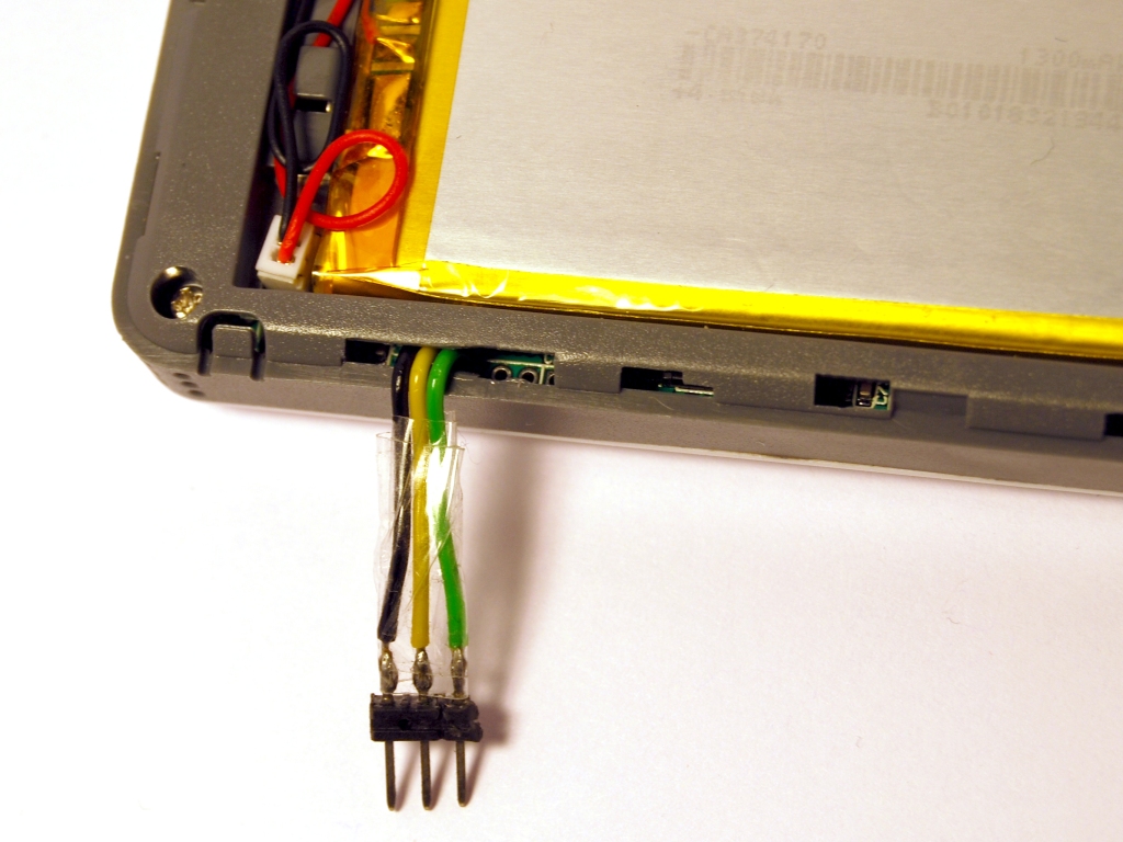
The naked header.
I hope to be able to make some sort of docking station for the DSO quad with a few rotary encoders and some buttons, for easy access at home and still keeping the device portable. But by checking the software I see that the SYS firmware does not have any serial port functions. As there is no GCC port of the SYS part of the firmware it is a bit harder than I expected to implement this myself. I don’t know why but I find it quite hard to add STM32 libraries to the build. Anybody willing to help?
Any other functions a serial port could be useful for? Implementing a small terminal or serial port monitor maybe.
Here is my version that I’ve used for debugging. It requires only cutting away a small piece of plastic and the adapter can be removed easily. It is held in place by the cover.
But obviously that needs some libc etc. for printf to function. My Logic Analyzer application has some debug output (not very relevant to the user, of course); if you are interested the source is here, check main.cc and libc_glue.c.
I was thinking about connecting one of these seeedstudio.com/depot/serial … th=139_142 to the internal port. This way, the DSO remains completely isolated from ground and there’s no risk for the PC.
Good idea, then it might even be possible to interface it with an Android phone. Good luck with fitting it into the case! Please submit some pictures if it works out. Happy hacking.
I saw the comment “USB_prop->init() is now commented out because it freezes at the moment” and that rings a bell. When I ported the DSO Nano firmware to GCC, I was also stuck at the USB initialization (gitorious.org/dsonano/dso-firmw … b64ebbd6bd
Not sure if this is the same issue here, but I thought I would mention it.
jpa, I have been trying to build your “logic” and “test_flash_size” applications from your svn repo, incorporating the code snippet above to output through the serial port. But I can’t get neither to build. “logic” is missing the libfixmath and baselibc libraries. And where is gpio_usart1_tx_mode() defined? I could probably guess what that function is doing and reimplement it but it would be nicer to get the complete code.
BTW is it necessary to set up the GPIO pins explicitly when you enable the USART?
EDIT: Never mind, I found your QuadPawn code on github which has libfixmath and baselibc directories that I can use. I guess you had those softlinked in your tree and not in svn. And I found the DECLARE_GPIO macro in gpio.h for generating gpio_*_mode(). For some reason I had to add ’ __exidx_start’ and ‘__exidx_end’ to the linker script, and an empty abort() function to “logic”, although the Makefile uses --fno-exceptions.
Compiling the test_flash_size code actually triggers an internal error in gcc 4.6.2, on “stack_pointer = &_estack;” in DS203/startup.c. I pulled in an __MSR_MSP() assembler function from the DS0201 code instead.
EDIT: This doesn’t happen when compiling “logic” which has the same code.
Now I try to write a string to the serial line, but I can’t get more than the two first characters through to my terminal emulator (gtkterm).
Hmm… I just bought the STM32F4-Discovery board that can be used as an SWD debugger. I see the SWD pins (PA13 and PA14) are used as GPIO input pins for the FIT and FUNC keys so SWD is probably disabled early in the bootloader in order to enable these keys. Anyone having experience with SWD on the Quad?
Hmm, the baselibc and libfixmath are defined using svn:externals. It should automatically fetch them when you do a svn checkout:
Fetching external item into 'logic/baselibc'
...

Fetching external item into 'logic/libfixmath'
...
You will have to cd to the baselibc directory and type make to build it first.
I have used CodeSourcery 2011.09 for building the logic app. It’s GCC 4.6.1. Apparently my code has some stuff that newer GCC versions complain about, I’ll fix those when I get around to working more on the logic app.
I just did a fresh checkout of logic and it built correctly, so all the files should be there.
Currently the QuadPawn code is the newest and cleanest. It also prints some debug to serial port at 115200 bauds, so you can use it to check that your serial connection works.
Thanks, I have dived into the QuadPawn code. But I laid the Quad aside again. Being sick and inside yesterday I wanted to see how difficult it would be to make some kind of port to the DSO Nano. I hoped to get to the point of booting up and showing the file selector, but I am now stuck at boot issues, maybe because I try to reuse binary code from the oscilloscope firmware in order to save space. But this topic is maybe food for another thread
In SVN you can just “svn checkout” the same http url to the directory. But I agree on the benefits of git, I mostly use svn for my own stuff that is sometimes random enough that I don’t bother to create a separate git repo etc.
Probably not too difficult actually. You can initially leave out all the amx_* files (platform libraries) to save space, because some of it is not even relevant for the nano. After you get the boot and LCD drawing working, the rest is probably very straightforward.
Hello guys,
have any of you succeed with bidirectional communication with UART? From the code snipped above it seems that you mainly use the uart for sending debugging messages out of the box. But I would like to receive some commands from PC and don’t know how to initialize the UART correctly.
Here is a code I have found somewhere, I tried to enable the interrupt on receive (bold font), but the intterupt function (USART1_IRQHandler) was never executed. To check this code I am sending periodically a text message to the uart port with the RX&TX pins connected together. I am able to see the transmission when I connect the oscilloscope probe to the TX pin, thus I think the problem is in uart control register being not set correctly.
/*static*/ void BIOS::SERIAL::Init()
{
  // Enable USART1:
  RCC->APB2ENR |= RCC_APB2ENR_USART1EN;
  // Set the baud rate:
  USART1->BRR = CPU_CLK / BAUD_RATE;
  // Enable the USART for both transmission and reception:
  USART1->CR1 = USART_CR1_UE | USART_CR1_TE | USART_CR1_RE | [b]USART_CR1_RXNEIE[/b];

[b]	// clear interrupt flag?
	USART1->SR &= ~USART_IT_RXNE;
[/b]
  // I guess these might mean enable pull up for RX and set TX as hard-driven output
  // AFOUT_10 probably mean b10, i.e. function 2, which is AF output, push-pull
  //gpio_usart1_tx_mode(GPIO_AFOUT_10);
  //gpio_usart1_rx_mode(GPIO_HIGHZ_INPUT);

  // TX is pin 9 on port A (PA 9)
  // RX is pin 10 on port A (PA 10)
  // Mask out any current values for the MODE and CNF values for pins 9 and 10
  GPIOA->CRH = (GPIOA->CRH & ~(GPIO_CRH_MODE9 | GPIO_CRH_CNF9 | GPIO_CRH_MODE10 | GPIO_CRH_CNF10)) |
              (GPIO_MODE_OUTPUT_MAX_2MHZ << PIN9_MODE_POS) |
              (GPIO_CNF_AF_PUSH_PULL << PIN9_CNF_POS) |
              (GPIO_MODE_INPUT << PIN10_MODE_POS) |
              (GPIO_CNF_PULL_UP_OR_DOWN << PIN10_CNF_POS)
              ;
  // Enable the pull-up for PA 10 (RX):
  GPIOA->BSRR = GPIO_BSRR_BS10;
  Send("DS203 Boot...");
}
Thank you very much Petteri, this helped me a lot!
But… In my STM library there are no such functions like NVIC_EnableIRQ or NVIC_SetPriority, when I was looking at your source codes, I noticed that some declarations are completely different from my, for example:
I simply cannot understand why is this so different… I gave up and extracted the necessary structures and functions from your stm library and placed it in my project. And voila, serial port is finally working!
@gabonator:
I thought your serial port <-> bluetooth adapter was very interesting indeed. A lot of laptops come with bluetooth now, and very few with actual physical serial ports, so this idea is great! And it gets past all the issues of grounding. Two goals with one kick.
A question though - why did you choose the OBS421 module? Reading your page “SerialOutput” the thing looked quite small, until I saw it beside the DSO! It was huge! I would (and am thinking of) using one of the smaller modules (not from connectblue BTW) and mounting it permanantly inside…
As an aside, I also like your revamped interface. It looks considerably nicer than the ‘out-of-the-box’ experience. It is on my ‘to-do-very-soon’ list…