lygra, I did what you said and the battery seems to stay charged after removal from the nano. Since I have no response from Sparkfun, the supplier, I suspect I am on my own. I did download the schematic and there seems to be a charge controller ahead of the battery both on the schematic and on the board. Someone here or elsewhere said he thought little of the Seeed charge controller and was going to use a different type. Any ideas? I do NOT know what the problem is and only have a vague idea how to track it down. Any other ideas?
Karl
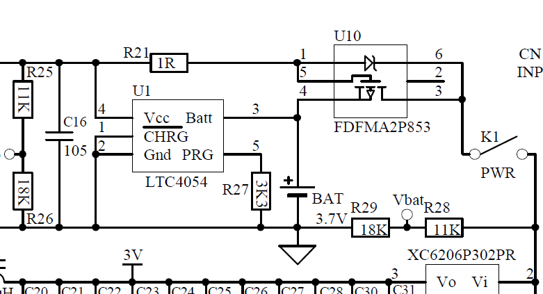
I have no opinion on the quality of the U10 and U1 chips shown below. Most Nanos don’t have your problem. There may just be a stray wire strand accidental jumper on the circuit board so you should look at it closely with a magnifying glass. You may also want to measure R27 to be sure it is 3300-ohms.
If it were me, I would cut the foil trace between BAT+ and U1-pin-3, install the battery and see if it runs down. If it does run down, then the problem is probably U-10 if no stray wire strands were found.
If it doesn’t run down, then resolder the broken trace and replace U-1.
If you look at V1 schematic, the part inside the dotted box does not exist according to ESP. You could maybe adapt that circuit if you can’t get the special chips. The disadvantage of the V1 circuit is that you can overcharge and damage the battery if you leave the live USB cable attached more than a couple of hours. That could also present a fire hazard.
Another way to determine whether your battery or Nano is at fault would be to measure current draw while the battery is in circuit. You would connect one of the battery leads in series with a DMM set for current measurement. A zero current draw (when the Nano is switched off) would suggest that the battery is at fault and so should be replaced. Otherwise it’s back to fault finding on the Nano as suggested by lygra.
As for the charge chip being no good - I would not trust anyone’s opinion on this unless backed with some compelling references. It’s not even obvious that the “best” charge circuit money can buy would perform better (battery longevity, safety, recharge time, economy) than the simple diode scheme used in the Nano V1. After all it’s the battery internal monitor/control circuit that gets the final word.
Lygra, I am on it with your impressive and rapid reply. Will advise. BenF, you are right about the “sour grapes” on the charge controller. I see more in the nano than most of the adapter chargers for modern day battery operated stuff.
One point: my nano is a V2-are the circuits in the power sections essentially the same?
Karl
I thought you had access to the V1.3A (V1 model) schematic and I was surprised not to find it on the download site. Attached is a copy of same. This is what I meant about converting to V1 charge circuit with a diode. This is also what BenF was referring to.
Yesterday I followed up on a post concerning whether or not the V1 battery has over-charge protection built in because that would eliminate the diode charge circuit overcharge situation. Still awaiting a reply.
v13aschem.zip (39 KB)
Battery was out for three days and held its charge from 4.11 to 4.09 volts with no load. Soldered the neg lead back to the board and stuck a milliammeter in series with the red lead and the board and had zero current. Put both leads back on the board and scope worked. Charged it up and have been monitoring Vp-p for the past two days. Will advise.
Karl
Must be success! Nano has been sitting since last Thurs and it was operational just now with 3.84 Vp-p. Must have been a whisker of battery wire that was draining everything. I looked with high magnification and found nothing on the boards that would short the battery and found everything nominal at the battery connection. But hey, I’m old and don’t see as well as I used to! Thanks to you all, the nano is back in business!
Thanks,
Karl
Update: The battery still drops dead in about 4 days. Turns out my trusty DVM has an inoperable amps/milliamps function so that test data was flawed. Got a SPST slide switch for PC board mount and installed it in series with the battery for a disconnect. The battery is now still in the green after three weeks.
Karl
Hi,
I don’t know whereto post this so i will post here, if is not the apropriate section please remove my post and point me to the correct section
I tried to upgrade my nano v2 to benf firmware and i had no succes thru a usb hub, the dfuse program was connecting to my nano but it would fail to write anything in the flash (the error was at the verification)
Then i connected the nano directly to usb port(without hub) and the upgrade went fine.
Hello,
Well no it does not work. Formated in exfat, fat16 which was successful.
Then downloaded the .rar file (which contains 39 .DAT files) and saved them on the SD card (2GB Scandisk).
Then tried to save a wave form, going to “FL”, press/hold M and it returns “file not exist”.
What’s my mistake here?
I don’t know what the problem could be as I tried the same steps you did and no luck. It’s driving me nuts. I bought the SD card from Seeed Studio as that one was supposed to work but nope!
Any ideas? Sent BenF a message months ago and no reply.
Cheers
Pete
When I save to a file on the SD card, the partition table on the SD card gets destroyed. I can’t read it on my computer anymore. :?
Old thread i know… but…
I managed to get my DSO Nano v2 back up and running, resoldered the b-switch to the board and the battery negative cable/lead to the pad. Really isolated with electrical tape so i didnt touched the positive pad. Really close to each other.
So how do i check battery charge and stuff? There are no indicators of that. It just says USB in the corner. Someone mentioned Vpp and such. Do i need to connect the leads? or is it shown internal in the menus?