DSO Nano v2 issues and FAQ

A little suggestion, how about offering a more expensive delux version? The nano is too cheap and I (and I think others) would like to pay more for even more features.

A deluxe version could have more expensive components and features like (just brainstorming):

  • A even fancier case (more steel or brushed aluminium) or more rugged
  • OLED screen
  • Two input channels
  • MMCX connectors
  • With two channels you could make it compatible with <LINK_TEXT text=“http://www.seeedstudio.com/depot/noninv … Path=84_91”>http://www.seeedstudio.com/depot/noninvasive-ac-current-sensor-100a-max-p-547.html?cPath=84_91</LINK_TEXT> so you can do true-RMS metering (power factor, kvar and such) like instruments like http://www.ordnancemarine.com/tams/a7061.html can. Of course you have to be able to handle like 400 or 690VAC atleast in x10 mode.
  • PC connection with software for live metering
  • Backlit buttons
  • Higher bandwidth


    Kind regards

    David

I won’t tell you that we are developing a similar one…

:o

hi. just received my v2 beta copy today: :wink:


first impressions:

  • like the metal case. feels nice and sturdy
  • slot for fixing is a nice touch
  • might be worth labelling the ports on the back cover
  • buttons are slighly misplaced. the down and left have a nice solid click wheras the other three have no tactile feedback
  • on off switch is a bit fiddly against the plastic


    overall, nice job! now to get on and play …

Hello, received my beta unit today.


While testing I’ve discovered an interesting issue.

While connected to usb and measuring with both probes connected to +5v I get some kind of short, multimeter reads 0.7A. Probably there’s a direct current path from - probe to usb+.

When disconnected from usb everything’s fine.

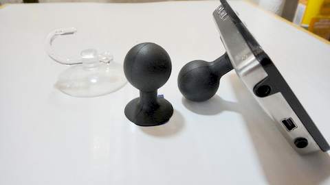
FAQ: My Nano needs a nicer stand


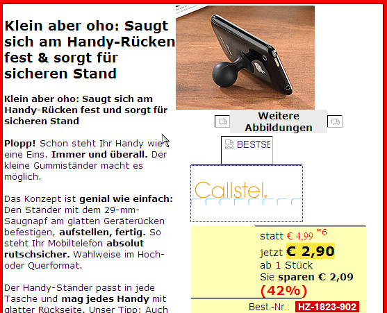
This is a really expensive sucker from Germany (2.90 EUR = USD 4$)

(the shop is : http://www.pearl.de - ArticleNr: HZ1823)

maybe you find something else in a mobile-phone-shop,

or something similar in an bathroom-shop

and use the good old Glue Gun to fiddle a little bit.

It is better than all other stands, because it is always together.
stand1.jpg
pearl_HZ1823.png

FAQ: I need more tactile feedback from the buttons


The Glue Gun with transparent glue helps to create 5 drops,

see pictures. It feels a lot better now for me.


Maybe you can use Epoxy cristal-clear too,

but the drop from a Glue Gun can be easy removed if needed.
GlueGun.JPG

Hi! With my DSO Nano V2 I received 2 rubber stickers. These are for what, exactly?


Thanks!!!

I paste the stickers on the stand, narrow one at the bottom and the wider one at the top of the stand.

Quite pleased with the DSO nano v2. Made a 10X probe and it works! Battery will not stay charged beyond 1.5-2 days sitting on the shelf. WTF with that? I would rather stay with the internal battery if there is something I could fix.


Karl

Sorry but, do you mean power off USB charging?

The nano goes from full charge to stone dead while off sitting on the bench in about 1.5 to 2 days. Not being used or being turned on.


Karl

Didn’t met that before… The one sitting by me powered up with dust.

How is the battery life?


Thanks for lifting the issue!

My V1 and V2 have both set for weeks while maintaining a charge (powered off, no USB connection). You should contact the place of purchase for a Nano replacement.


To determine if the battery is really fully charged, you can measure the probe calibration output signal of the Nano with the Nano. The Vpp should reflect the actual battery voltage. My V2 measures Vpp = 4.20V with full battery bar. What does your’s measure with V/Div=1V, T/Div=500us, and FR=1Khz


If replacement is not possible, and if you can solder, then you can isolate this problem yourself. Fully charge the battery, then open the case (possibly voids any warranty) and unsolder the battery red lead as shown in the attachment. Wait a couple of days and then solder the red lead back on the Nano. If the Nano works, then the Nano is the problem. If the Nano is dead, then the battery is the problem. Take care to not short the red and black leads together while unsoldering or soldering.
NanoV2.png

ESP, the above quote describes that Seeed is in possession of BenF’s latest released open source code (v3.13) which is ported to IAR v6.1. Would you please post that at http://code.google.com/p/dsonano/ for the benefit of all concerned. Thanking you in advance.

ESP, you have always been very candid in other posts. Would you please elaborate on the “some third party code included in LIB” so we can all understand just what is going on here. Are you referring to STmicroelectronics code, or some other code? Please clarify so that we can understand why F/W that has been described as open source now appears to have some third party LIB restrictions.


It is untimely that you have not updated http://code.google.com/p/dsonano/ to include the latest 3.0.1 version of DFU (it supports Win7, 64-bit OS, and installs the appropriate drivers automatically). Much effort has been expended by all parties (Seeed Studio included) to get the DSO Nano into it’s current functionality. Perhaps you can help to tie up all these loose ends so that development from BenF’s v3.13 open source code can proceed smoothly without all these bumps in the road.


Thanks for all the good work and effort that Seeed Studio has performed to get this project where it is today.

We have upload the laest version source code of Benf firmware (V3.13) at:

https://github.com/Seeed-Studio/DSO


And, I want to clarify all the Development Process of DSO and related Sourcecode.

As in the package you have noticed, DSO series are developed by Chai Xiaoguang (Bure) and his team (e-design). Seeed Studio’s role is more like a producer of a movie, we coordinate the resources, bring it up to reality products, collect the feedback and work with e-design to improve. It’s similar to other cooperative projects like with dangerous prototypes.


And, The whole soucecode is : .DFU(programmed by e-design)+ .lib&.app. The .lib and .app are totally open source, But as the .DFU, Because it is “third party code” as ESP said ,We can offer the .dfu file, But we have not get the authorization to Open it’s source .

Thanks for providing the GitHub link, that must be fairly new. I really appreciate whoever took the time to set this up.

Thanks for your clarification, it really helps to fully understand the big picture. By .DFU, are you referring to the loader software that talks to the DFuSe Demonstration utility, or is there more to it such as an Operating System? I noticed that there is no .DFU in the downloaded git, only BenF’s Lib.dfu and App.dfu.


“The Development Guide of the DSO Nano” has no reference to the .DFU. Are you saying that the .DFU is available as a binary but the source for this .DFU is not available?


How would the .DFU be loaded into the DSO Nano? Is there another STMicroelectronics application (such as DFU Tester) that can load the .DFU? I am asking just in case the current DSO Nano .DFU ever gets damaged. Is there a location where the .DFU can be downloaded?


Thanks again for taking the time to respond and share.

lygra, I did what you said and the battery seems to stay charged after removal from the nano. Since I have no response from Sparkfun, the supplier, I suspect I am on my own. I did download the schematic and there seems to be a charge controller ahead of the battery both on the schematic and on the board. Someone here or elsewhere said he thought little of the Seeed charge controller and was going to use a different type. Any ideas? I do NOT know what the problem is and only have a vague idea how to track it down. Any other ideas?


Karl

I have no opinion on the quality of the U10 and U1 chips shown below. Most Nanos don’t have your problem. There may just be a stray wire strand accidental jumper on the circuit board so you should look at it closely with a magnifying glass. You may also want to measure R27 to be sure it is 3300-ohms.


If it were me, I would cut the foil trace between BAT+ and U1-pin-3, install the battery and see if it runs down. If it does run down, then the problem is probably U-10 if no stray wire strands were found.


If it doesn’t run down, then resolder the broken trace and replace U-1.


If you look at V1 schematic, the part inside the dotted box does not exist according to ESP. You could maybe adapt that circuit if you can’t get the special chips. The disadvantage of the V1 circuit is that you can overcharge and damage the battery if you leave the live USB cable attached more than a couple of hours. That could also present a fire hazard.
charge.png


Another way to determine whether your battery or Nano is at fault would be to measure current draw while the battery is in circuit. You would connect one of the battery leads in series with a DMM set for current measurement. A zero current draw (when the Nano is switched off) would suggest that the battery is at fault and so should be replaced. Otherwise it’s back to fault finding on the Nano as suggested by lygra.


As for the charge chip being no good - I would not trust anyone’s opinion on this unless backed with some compelling references. It’s not even obvious that the “best” charge circuit money can buy would perform better (battery longevity, safety, recharge time, economy) than the simple diode scheme used in the Nano V1. After all it’s the battery internal monitor/control circuit that gets the final word.