Hi RoboKaren,
Changes in the DSO Nano 2.3
Seeedstudio has been nice enough to send me a prototype of the new DSO Nano.
It has DSO201 Oscilloscope Lib v2.22 and DSO201 Oscilloscope App v2.4 firmware loaded.
This may change, so my comments below apply to what I have in hand.
Physical
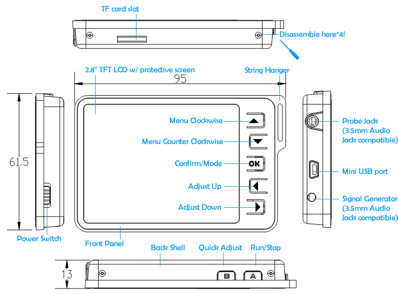
The 2.3 has a metal case, and is about 20% thicker and “taller”, but 20% “narrower” than the original. The power switch is now a metalized knob on the lower right side of the case; there are 5 navigation buttons arranged vertically on front to the right of the color LCD display, and two buttons on the top right side. The input connector is on the upper left side and there is now a connector on the bottom left side for the test signal out put. A mini USB connector is on the left side between these two. The micro SD slot is on the bottom.
The DSO Nano is now strong and stiff, significantly more rugged than the original. The power switch is easier to operate. The navigation buttons are part of the front panel, instead of separate buttons. I find them easier to use than the previous version which had them in a square pattern. Neither version is particularly dust or moisture proof, so if the scope is used in a dirty or wet environment, I would put it in a clear plastic zip bag.
Circuits
The differences in the circuits are mostly to the power supplies, with some improvements to other circuits.
There is now a regulated battery charger (U1), and switching between battery and USB power (U10). This will give the battery a long life and will not overcharge it. It also allows using the DSO Nano on the USB power while charging the battery. The charge current is limited to 300ma. This means that a discharged 500mah battery should recharge from the USB port in less than 2 hours.
For the +/- 5 V supply there are two new ICs (U7, U8) replacing the old (U7). These are switched capacitor supplies which actually double the input voltage (from the Battery or USB), so the voltage can actually be higher than the “5V” on the schematic.
The calibration signal output and the serial port (CN5, internal) use a new IC (U9) as a buffer. This is operating from the Battery or USB Voltage, so the test signal’s amplitude will be higher when using the USB for power (close to 5V P-P) and lower when using battery power (3.7V P-P). This applies to the serial TX output as well.
The Attenuator section (input gain) has some variable capacitors added to allow more accurate adjustment of compensation for stray capacitance and tolerances (i.e. when looking at a square wave the tops can be made flat).
In addition to the JTAG connection (CN7 internal), there is now an ISP (In-circuit Serial Programming) connector (CN4 internal). This can make reprogramming the Processor much easier.
Everything is now on one PCB (the original DSO Nano had 2 PCBs joined by a connector).
Firmware
I don’t know the details of what changed in the code, but can tell you that it now obviously can support ISP (I don’t know if has been implemented).
Most exciting is a much better display of changing signals such as audio. The waveform display is now light blue; instead of the green of the previous DSO Nano There is also a new function: Fit, in the upper left window of the menu where you select the sweep types.
What is the “Fit” Function? Automatic Settings! When Fit is selected, both the input sensitivity (V/Div) and the sweep (us&ms / Div) automatically adjust to “fit” the signal on the screen. You can manually adjust these settings, but after a short time the “Fit” will readjust them again. This works well, with a good tradeoff in timing between changing the settings to how fast and long the signal is not optimally sized. There is enough time for some peaks without constantly switching between settings.
I will be doing some more testing and evaluation shortly and post my findings here.
Shazam


 I saw the DSO demonstration in my arduino course. It’s very usefull to work. the DSO is pratical and good to work fine to automation projects.