Hi all,
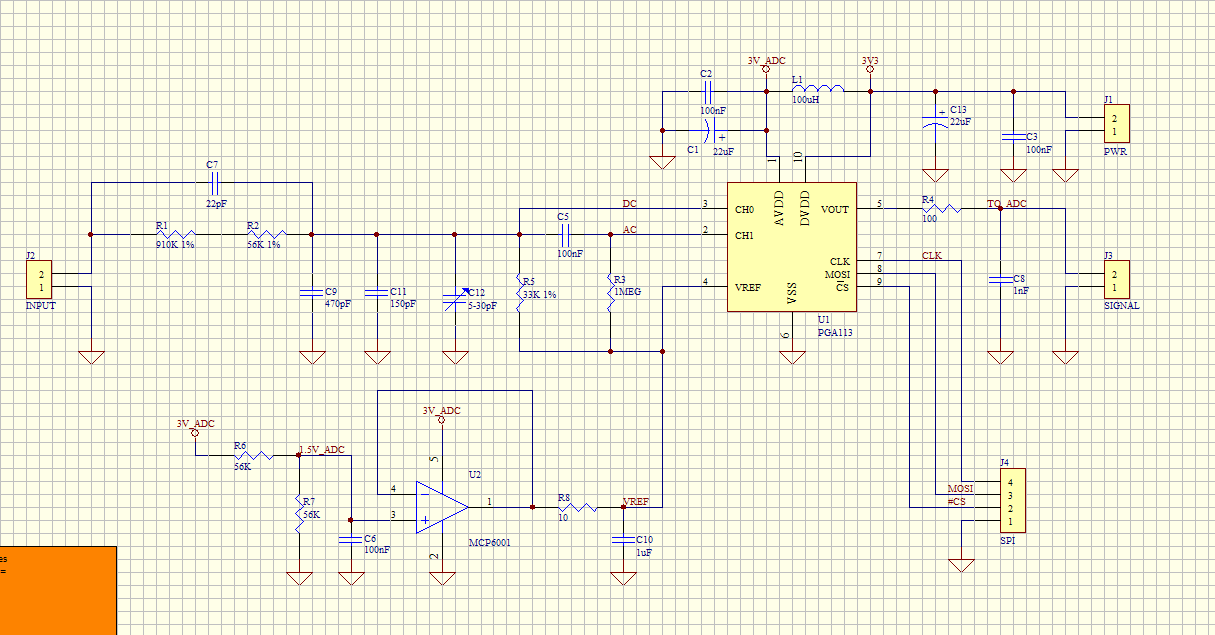
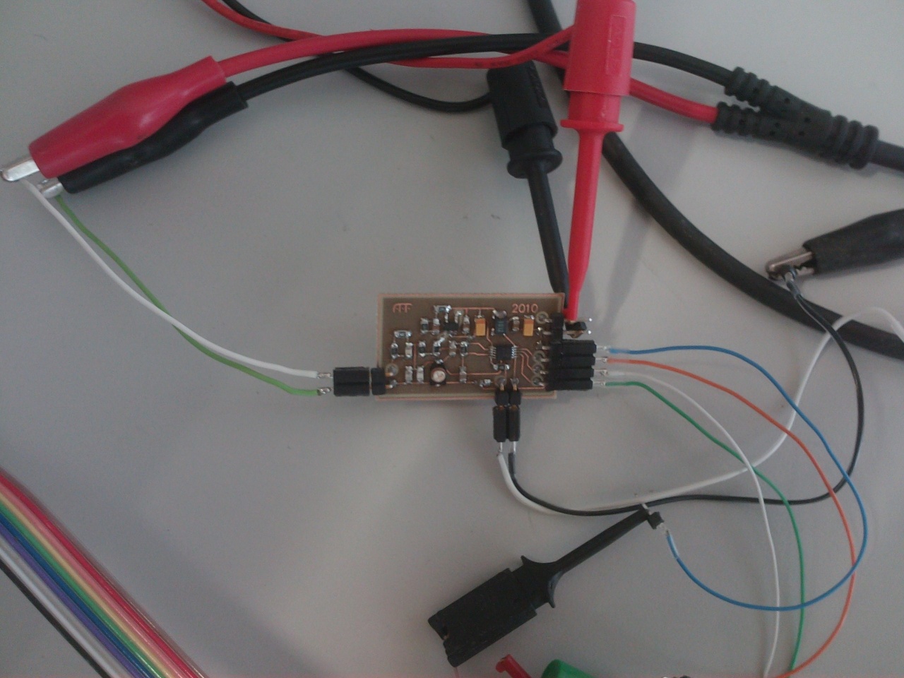
finally i got some time to do some test to the board i’ve built. The final schematic has been changed slightly in order to include a trimmer to ease the probe compensation. The designed PCB was designed with the time as the main constraint. So don’t expect a PCB design artwork here. A photo and schematic are included below.
In order to test the board, i used a Bus pirate (SPI commands), a multimeter, an oscilloscope and a spectrum analizer. The spectrum analyzer has an input impedance of 50 Ohm, so i also used a buffer between the PGA112 and the spectrum analizer.
Consumption (PGA + LMV321)
-Active: 1.4 mA
-IDLE: 0.5 mA
DC behaviour (DC measurements)
More or less as in the previous post. Expect a 5-10% error with 1% resistors and a usual circuit (R < 100K) under test.
AC behaviour
Tested first the compensation adjust with the trigger. Source was a square signal of 0.1 - 10 Vpp. It works, peaking is completely eliminated across tested frequencies (10 kHz - 500 kHz) and voltages. The x10 probe was not tested.
The frequency behaviour was observed for the 100 kHz - 1 MHz range. I would like to test with lower frequencies, but unfortunately, the sweep generator started @ 100 kHz.
When amplification was small (x1 - x32) the amplification gain was stable and the curve had 1 dB between peaks which translates into a 10% error for the full range. For the useable range of 100 - 200 kHz, the curve amplitude was < 0.3 dB which is approx. 4% of gain error.
For the higher ranges of amplification (x64 - x128) the amplifier was low pass filtering (approx. 3 dB @ 500 kHz).
I would like to post all the measurements in detail, but i don’t have the time to do the proper documentation. The circuit works (although it has to be tested with the x10 probe) and the results are very promising. Obviously, i would like to make a comparison between the actual DSO stage and the proposed one, but time is a scare resource these days, so i live that task up to Seeed or any of you with the proper equipment.
Needless to say, all the schematics and PCBs are with no license of any kind. Feel free to ask for the PCB & SCH file (protel) if you feel the need to.
P.S. All dB values are refering to a voltage signal, not to it’s power. Amplitudes are calculated as follows dB = 20 log10 (v).
Slimfish