In version 3.61, the buffer indicator at the bottom of the screen. What does the yellow filled box represent? It goes away while scrolling the buffer and then returns once the scrolling has stopped. The yellow outline box most likely represents the viewing window of the display but the solid box inside puzzles me.
The outline is as you suggest, the viewing window and the solid box represents how buffer data is distributed (size and position) within this window. The “blinking” you see when repositioning trigger is just an unintentional artifact relating to how the display is refreshed.
Hello. While writing code.google.com/p/benfwaves/ I am looking for more information on vertical resolution of the DSO Nano V2. Specifically:
How do I determine vertical resolution? Is it affected by volts/div, or the attenuation field?
In the “Buffer Usage and Priority” section, it says that in fast sample mode, sampling rate can be increased at the expense of reduced sampling depth. Does this affect vertical resolution?
It says that the purpose of the sampleDiv field is to distinguish between normal and fast mode. However, for time scales below 50 us, it seems that there is no difference between the fast mode sampling frequency and the normal mode sampling frequency. Will a difference still show up between sampleDiv and timeDiv in the XML? If not, how does one detect fast mode in that case?
Vertical resolution can be determined from choice of V/Div and attenuation. In the “Voltage range and sensitivity” section (3.6 users guide) you will find true vertical resolution (as limited by hardware) specified in the “Sensitivity” column for all valid combinations of V/Div and attenuation.
Sampling mode/rate affects the time axis (horizontal resolution), but not vertical resolution.
The sampleDiv field (as used in the XML file) reflects actual horizontal resolution used during acquisition. The table in the “Buffer Usage and Priority” section shows how this relates to sampling rate. At a T/Div of 20us and less we’re at the hardware limit (1 Ms/s) and so there is no difference between fast and normal for these rates. Another way to look at this is to say that sampleDiv determines actual horizontal resolution whereas V/Div is the preferred viewing resolution. Note also that true sampling rate can be calculated from sampleCount / timeRange irrespective of user preferences.
I just got a DSO Nano and upgraded the firmware to 3.61. After I load a waveform (either Load Pri or Load Ref), the trigger level is thrown way out of range. For example, I took a 60Hz background signal in 50mV/Div and saved it with a -20.0mV trigger level. When I load the signal as a reference waveform the trigger gets set to -30.4V. This makes the reference feature almost pointless since it would take me an hour to adjust the trigger level back close to -20.0mV in 50mV/Div so I can trigger the real time signal. And unfortunately adjusting the VD just makes the trigger level astronomical since it scales with it (-1.79kV at 10V/Div).
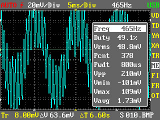
I can not duplicate your problem. As seen by the attached views, the trigger level always assumes the last thing loaded. Perhaps you have some YA offsets involved.
First view = 10xmlprimaryload.jpg = file010.xml loaded into primary buffer.
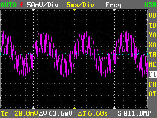
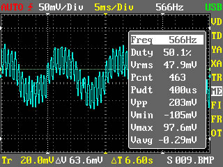
Second view = 09xmlrefload.jpg = file09.xml loaded into Reference buffer.
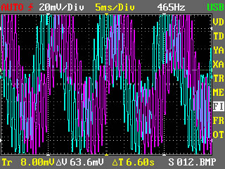
Third view = both10primaryloadedlast.jpg = file09.xml into ref buffer first, file10.xml into primary buffer last. I believe that the phase shift is due to different trigger level and/or signal variations between captures. These two captures were obtained by placing my finger on the probe tip. This view also demonstrates why I feel that it would be good to separate the vertical offset and V/Div for the two buffers.
See next post for xml files zip attachment (limit of 3 attachments has been exceeded). If we all use these files then we can describe any issues in common detail.
I found that then changing Gnd position V1 and V2 cursors not moved with GND level and I need to move them separately. Is this a bug or the future? Same with Vert Pos.
Both voltage and time cursors are disconnected from the waveform position by design. This is how most scopes work and I also think it makes sense more often than not. If we were to link cursors to gnd/vert pos (and V/Div) we would have issues with pushing cursors off screen and this would complicate the user interface (where are my cursors?).
Knowing how it works, you can adapt usage accordingly – set gnd/vert pos first and then position your voltage cursors.
benf- how hard would it be to put a few software attenuators in there for useing the current probe, that convert 10mv per 1 amp and 100mv for 1 amp, i keep confusing my self with milivolts only while using a current clamp… thanks for the hard work you did with the 3.6 series, i’ve been using the nano instead of my pico scope for quickwaves at work, its nice when i can pull something out of my pocket to look at a quickwave and not have to clean up 10 minutes worth of test leads like i do with my other scopes
That would be a very important application of the Nano because clamp on ampmeters are extremely useful for troubleshooting many current demand situations. They are used to observe current waveforms in addition to DC values. They have become another valuable o’scope probe.
Maybe BenF would consider this possibility in the measurements function, with a new measurement value that converts the milli-volts to ampere values.
ingra- how would he do the ranges- there are 3 common ranges 1mv=1amp 10mv=1amp =100mv=1amp, it wouldnt be usefull unless all three were implimented, i use the first one for starter relitive compression checks, the second one for alternator ripple measurements and diesel injectors… and the third is the most used for coil/injector/iac and such… i think you have a good idea, i guess the options would be 10amp(100mv=1A) 100amp(10mv=1A) 1000amp(1mv=1A) these would be your max current ranges in those ranges
After expending more thought on this matter, your idea of an attenuator might be the better approach for evaluating amp clamp waveforms. It could be handled as a configurable custom probe (in lieu of 1x and 10x) using user configuration parameters. This would also allow users to connect custom probes with alternate attenuation for voltage applications. If it can be done for one custom probe, then a couple of custom probes could also use the same structure.
A configuration pop-up that would allow the user to select input ratio choices of 1,2,3,5,10,100,1000 and then allow the user to select output ratio choices of 1,2,3,5,10,100,1000. Also allow the user to select the output choice of V or A. Now the input voltage would be scaled for this custom probe (using the user selected ratio), the vertical units could display V or A, and this custom probe could be saved with the configuration data.
BenF is much better at sorting out the menu organization and he most likely has a better idea. In summary, the custom probe concept would have many applications beyond amp clamps.
Improved support for non standard probes is probably a good idea, but it will be a challenge to implement this in a way that will be intuitive, logical and easy to use. Changing the user interface to use terms like Amp/Div, delta amps and amp trigger level seems awkward. Also we would not want to limit ourselves to amps, but also consider that custom probes may be used for pressure, energy, mass, force and what not. As it is now we can use any such probe as long as they output a voltage/frequency that fit within Nano hardware constraints, but then measurements may require a final conversion step (perhaps something for the XML analyzer).
A custom probe with user configurable gain/attenuation might work and I’ll keep that in mind for future upgrades.
Maybe this would be much simpler if the user just configured the ratio units required to reflect the desired units in volts, milli-volts, etc, and then calls the voltage units by another name such as amps, pressure, strain, or what-ever units. Then the Nano can stay with voltage units displayed. For example for 10mv = 100ma, then the user just selects a probe ratio of (1 input unit = 10 out units) probe ratio and the 10mv would convert to 100mv and the user would call that 100ma, or in other examples other 100m-Units.
Hello, I think brandonb aproach would be much simpler for an amp probe like the one on this video. youtube.com/watch?v=gMq26dubD5I
thanks a lot for your great improvements.
It would be also be nice to have a possibility to save several calibration settings (like with the preferences, one as power on default and some ‘customized’). This wound help to re-calibrate the whole system of probe and oscilloscope for different probes.