Version 3.40 has been out now for about two weeks and has been downloaded (and I hope successfully installed) by more than 400 unique users. At present there are no open issues (no reports of error) so unless a lot of users out there keep issues to themselves, the firmware appears to work as advertized on both V1 and V2 hardware.
This is a minor update with a couple requests collected from forum users. New functionality includes the following:
Support loading (profile, waveform) from arbitrary named files
Allow sensitivity lines to remain visible when adjusting trigger level
Cancel FIT mode (change to AUTO) when manually adjusting V/Div, T/Div or trigger level
A complete distribution is attached for download, including an updated users guide.
Update 2011.01.02 APP and LIB V3.42
Support SD card hot swap
Updated firmware users guide
Update 2011.01.09 APP V3.43
Fix issue with inaccurate sample time interval for 2s/Div and 10s/Div
Adjusted logic for trigger icon coloring (always go red when trigger absent)
Thank you very much for your improvements!!! .Now it is going to be much easier to work with the Nano on the field, where time is expensive.
Would it be possible to cascade two Nanos? I think this feature may involve hardware and not software, but would it be possible?. Thank you again for takin our request into consideration,
happy new year
Thank you, thank you, thank you very much. The Nano has been transformed into a useful and professional tool. You have carved that proverbial diamond out of the rough.
I am not at a location where I can change to V3.41 right now but I have viewed the PDF file. I really like the red filename concept (not in this version). Perhaps you could include the version number in the filename and first document page of future PDF document releases. Your minor updates will be demonstrated in the next tutorial presentation at youtube.com/user/lwgraves?feature=mhum#p/p I will also create a tutorial #0 explaining how the lessons will adapt to future firmware updates.
Once again, job well done.
Oh yeah, a lesser important event, Happy New Year
There are currently no provisions for choice of language, but adding such a feature would be within the scope of what the Nano can do. Would you not think however that translating the user guide is more of a priority?
Tonight while completing tutorial #7, I noticed that when in AUTO mode, the trigger edge symbol fails to turn red with loss of trigger. Appears to be an oversight from previous version.
When in AUTO mode, the Nano will always trigger (as it is forced after 100 ms if no trigger is found) and so the waveform display will be updated and the trigger symbol stays green. The idea here was to keep it simple: If the trigger symbol is green, the displayed waveform is “fresh”. If the trigger symbol is red, we’re looking at “old” data.
My concern is that the user may be looking at a jittery waveform and not realize that changing the trigger level/sensitivity may very well improve the waveform stability. By definition, AUTO means the display is continually being refreshed. The following example demonstrates my opinion:
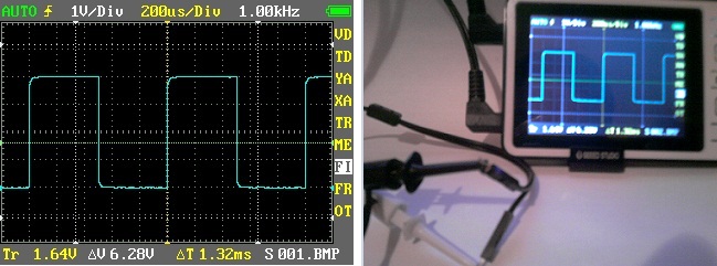
Input the 1Khz waveform with VD=1V/Div and TD=200us/Div and then raise the trigger level well above the signal, then observe for 30 seconds. You will observe two things, waveform jitter is present (not triggered) and the transition symbol will occasionally flicker trying to show red.
Now place the trigger level inside the waveform and the waveform becomes rock steady. A complex and/or unstable input signal waveform could have much more dramatic behavior while not being triggered in the AUTO mode.
Hello Benf
The firmware v3.42 Benf not working properly on Nano V2, contains noise … the larger the scale v / div bigger the noise.
I did a test without USB power (using the internal battery) and the probe connected to the frequency generator with a 1 KHz test signal.
I found this picture:
The pictures you posted look as expected and suggest your Nano works just fine. Apart form this, your question is more of a guessing game:
Are you suggesting that the firmware works for V1 hardware only?
Are you suggesting that your Nano is working better with the stock firmware?
What is the nature of the noise and how is this different from what you expect?
What do you measure and how do you take these measurements?
How can you be certain that the noise is not part of your input signal?
If you think this issue is specific to the 3.4x firmware, posting in this thread is fine. If it is a general question on best practice for noise elimination, it may be more appropriate to create a new topic. In any case you need to explain in detail what the nature of the problem is or else no one will be able to give you meaningful replies.
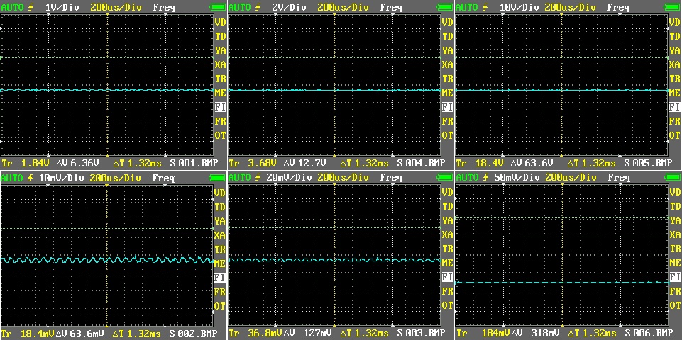
I did a test without probe, No load.
Only by adjusting the different scales of v / div.
The noise does not happen with firmware v3.33
Here are some pictures:
There is likely to always be some ripple/noise on the input and this is particularly noticeable with a low mV scale and a floating input signal. Much of this is eliminated when you measure a low impedance source.
In firmware versions prior to V3.4, a pull-up resistor was (incorrectly) active on V2 hardware ADC input and so would limit floating noise. Re-enabling this pull-up however is not a good option, because the pull-up resistance interacts with source input. For a low impedance load this is less of an issue, but for moderate to high impedance loads, this may cause highly inaccurate measurements.
To reinforce Bens excellent answer, I set up my Tektronix TDS210 ($1000 scope with no probes connected) to 20mV/Div (doesn’t even go down to 10mV/Div) and 250us/Div (doesn’t have 200us/Div choice) and I found random noise (grass) of 0.6 divisions = 12mV. On the Nano (with no probe connected) with 20mV/Div and 200us/Div, delta-V cursor measurement = 4mV and 4mV noise viewable on the screen (0.2 divisions). I can also view ticks on the Nano screen from the frequency generator of the Nano with delta-V = 11.2mV. I know these ticks are from the frequency generator because they follow Freq Out changes on the Nano.
So the Nano actually performs better with less background noise displayed. Of course this may look better on the Nano due to the limited sample rate of the Nano. Your environment will also greatly affect these results. I have two computers running within 3 feet and that will have influence on the results.
Bottom line, the Nano is holding it’s own in this regard and this is not an issue.
Thanks for another upgrade. All users should review this Firmware User’s Guide carefully because BenF has improved several topic areas and those improvements can help you to better understand the device capabilities.
Yes, both IO’s are considered. A check is performed to see if the two IO’s (PA0 and PA1) are connected and this now determines how they get configured.
I seem to be having a triggering problem in the ‘single’ mode. It’s probably my lack of experience with this firmware.
Triggering:
I am looking at current draw at power on of a device. I have a 10 ohm resistor in series and I’m measuring voltage across it with the DSO Nano. First of all, and correct me if I’m wrong, but the trigger level seems to change depending on the volts/div setting which is frustrating. I get the unit set up to trigger and display a waveform. I change the Volts/Div, repeat the power-on event and no trigger, try the event again and sometimes I get a trigger. I have to go back and play with the trigger level to get it to work. I spent 80% of my time trying to get the DSO Nano to trigger properly on a single shot positive-going waveform.
Trigger sensitivity is a mystery to me - I have never seen that function on a DSO from a major manufacturer (but I have only seen Tektronix and Instek). Can anyone explain this to me? This could be a large part of my problem.
Calibration:
I tried to cal the unit and the results were strange. Should it be cal’d using AC or DC as an input? If AC then I would like to see a RMS as a measurement in the 'ME" screen. Using DC I can cal it to one voltage (for instance 1V on the 2V/div scale), but when I apply 5V DC to the input the reading on the DSO is wrong by at least 0.5V or more. Here is an example of my results calibrating the 2V scale with 10V DC input: