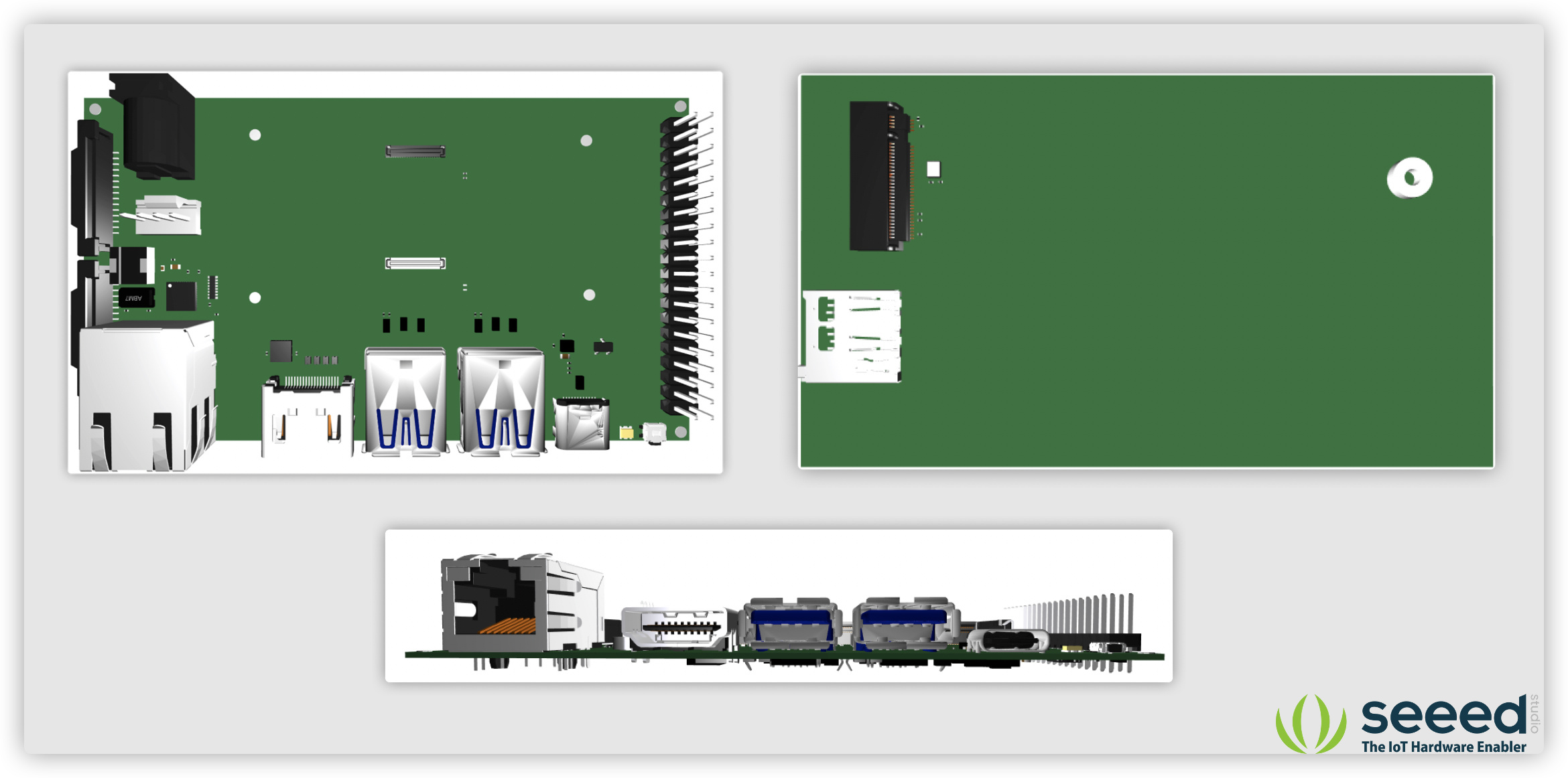
As the new COM4 is about to be available, and it will finally have a PCIe x1 available on the compute module, Seeed is planning to design a carrier board for COM4 to utilize its new features. The rough design is shown below for discussion. What features do you want for the new carrier board? Please leave a reply and let us know. Any suggestion or advice will be appreciated.
The idea is to have one single cable for power, display and touch. I have one similar screen and its works that way connected to a laptop running on Windows.
@binbin.yuPoE as same the RPi 4 footprint will be a nice addition since the chipset support it. also, a power switch or header pin’s that can turn on/off the power will be useful.
@binbin.yu Oh great, I didn’t notice that, Thanks. also if possible please release the STEP or CAD File, it comes handy when designing products with that.
I would add support for power via PoE. Also, I would add a small 3-port gigabit switch, with 1 port internal for the CM4 board and the two others as external ports. PoE in on one port and PoE out on the second. Get rid of the SD card reader and use CM4 with eMMC.
This looks pretty close to what I’m looking for, so hopefully it’s still under development!
If i was doing the component layout I would do it like this.
M.2 mount on the bottom
all the standard I/O (usb, power, ethernet, hdmi, micro SD) all on one of the long edges, even if that means making the pcb slightly larger or mounting components on both sides. Maybe even making all the usb ports usb-c to save space.
GPIO on the other long edge
Both csi connectors that can be used for camera modules on one short edge, and spaced out properly so that HQ camera modules can be mounted side by side with the short 38mm ribbons without issues. (edge mount connectors)
with an m.2 and all the the standard I/0 on a long edge, people can finally make a nice looking mini desktop, or development server, without using the kludgy usb 3.0 C shaped adapter.
with the GPIO on the other side, people will have easy access to the pins if needed. It would also probably go a long way towards having an engineering session finish without cable spaghetti all over workbench/desk. Just having holes for GPIO pins might be a good option as well, as I see a lot of people either not using them or at all, or swapping out for a right angle connector like on the 400.
The properly spaced csi ports means people should be able to make nice compact computer vision projects.
Hi…there is an exceptionally decent KiCad model accessible. I don’t think it is advanced science to make something straightforward utilizing a CM4.
However, after I took a gander at the Compute Module IO board there is no sense in building my own. The technicians is truly astute and you can undoubtedly make HAT style sheets that have connectors on the left and inverse side of the board as it were. The Audio injector sound card would fit consummately giving both sound in and sound out. In reality most HAT cards would have a pleasant mechanical spot to broaden usefulness. So investigate these befor taking the jump to make your own.