Connect two pins with a Switch

Hi!
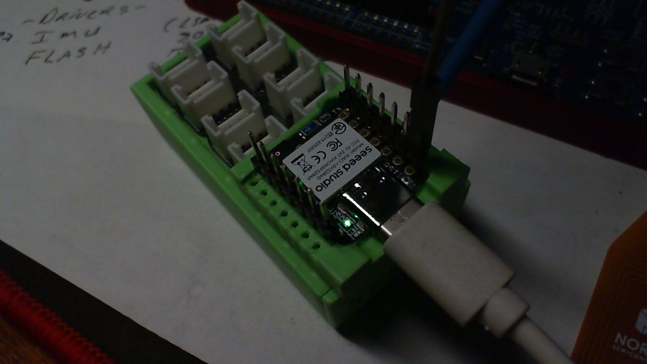
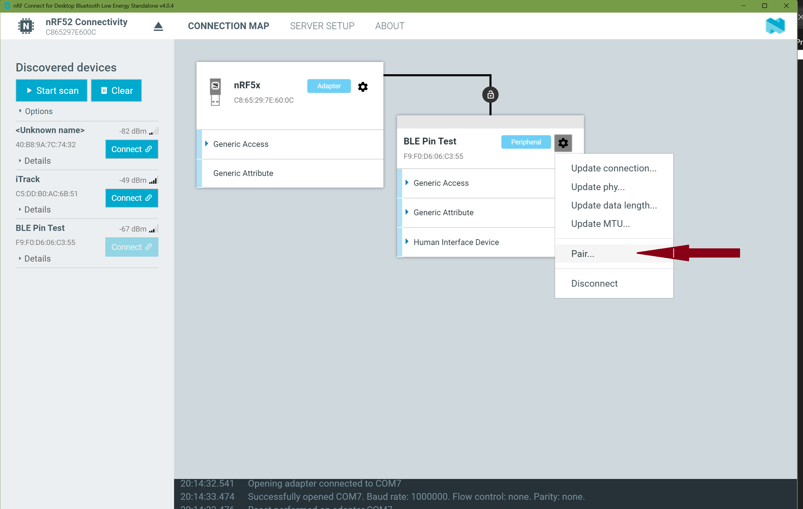
I have a software in my Seeed XAIO nRF52840 Sense that should send a letter over BLE when two pins are connected.

But I cant find a way of make the board understand when they are connected.

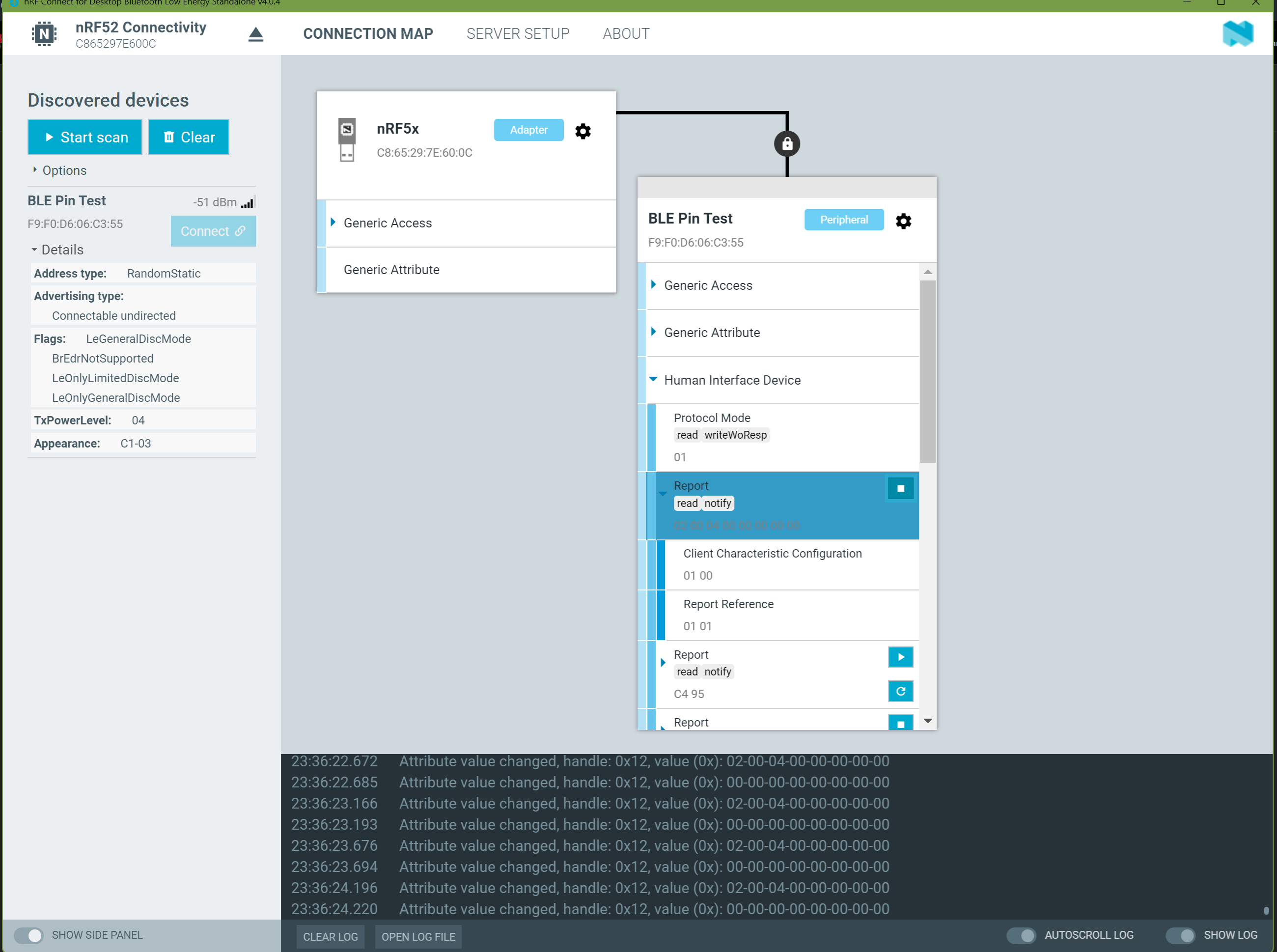
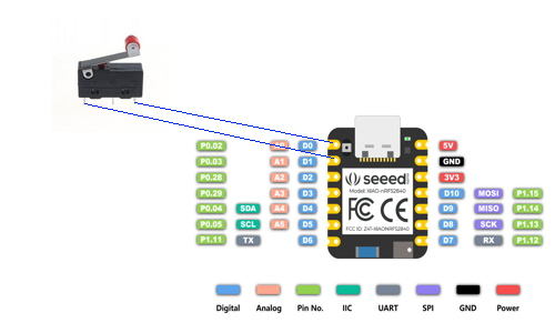
I have put an open Switch between P0.02 and P0.03 and when the switch are closed the software should recognize this and send a letter, in this case a “A”.
I use Arduino to code, but cant make this work, when connected via serial or BLE.
Please help.
Regards
Fredrik

#include <bluefruit.h>

// Define pin numbers and their aliases
#define PIN_P0_02_A0_D0  18  // P0.02, A0, D0
#define PIN_P0_03_A1_D1  19  // P0.03, A1, D1
#define LED_PIN 13          // LED pin (could be D13 or any other available pin)

BLEHidAdafruit blehid;
bool bleConnected = false;

void setup() 
{
  // Start serial communication for debugging
  Serial.begin(115200);
  while (!Serial) delay(10); // Wait until serial is ready

  // Initialize Bluetooth
  Bluefruit.begin();
  Bluefruit.setTxPower(4); // Adjust transmission power

  // Set the name of the Bluetooth device
  Bluefruit.setName("BLE Pin Test"); // Change the name here!

  // Initialize HID (keyboard functionality)
  blehid.begin();

  // Connection callback
  Bluefruit.Periph.setConnectCallback(connect_callback);
  Bluefruit.Periph.setDisconnectCallback(disconnect_callback);

  // Start advertising immediately when the device is powered on
  startAdv();

  // Initialize P0.02/A0/D0 and P0.03/A1/D1 as inputs with internal pull-up
  pinMode(PIN_P0_02_A0_D0, INPUT_PULLUP);
  pinMode(PIN_P0_03_A1_D1, INPUT_PULLUP);

  // Initialize LED_PIN as output
  pinMode(LED_PIN, OUTPUT);
  digitalWrite(LED_PIN, LOW); // Turn off LED initially

  Serial.println("Setup completed");
  // Test to blink LED to ensure it works
  for (int i = 0; i < 5; i++) {
    digitalWrite(LED_PIN, HIGH);
    delay(500);
    digitalWrite(LED_PIN, LOW);
    delay(500);
  }
}

void startAdv(void)
{  
  // Add advertising data
  Bluefruit.Advertising.addFlags(BLE_GAP_ADV_FLAGS_LE_ONLY_GENERAL_DISC_MODE);
  Bluefruit.Advertising.addTxPower();
  Bluefruit.Advertising.addAppearance(BLE_APPEARANCE_HID_KEYBOARD);
  Bluefruit.Advertising.addName();

  // Set advertising settings
  Bluefruit.Advertising.restartOnDisconnect(true);
  Bluefruit.Advertising.setInterval(32, 244); // Unit in 0.625 ms
  Bluefruit.Advertising.setFastTimeout(30);   // Number of seconds in fast mode
  Bluefruit.Advertising.start(0);             // 0 = Advertise until connection is made
}

void loop() 
{
  // Read status on P0.02/A0/D0 and P0.03/A1/D1
  int pinStatusP0_02_A0_D0 = digitalRead(PIN_P0_02_A0_D0);
  int pinStatusP0_03_A1_D1 = digitalRead(PIN_P0_03_A1_D1);

  // Print status on P0.02/A0/D0 and P0.03/A1/D1 to serial monitor
  Serial.print("P0.02/A0/D0: ");
  Serial.print(pinStatusP0_02_A0_D0);
  Serial.print("  P0.03/A1/D1: ");
  Serial.println(pinStatusP0_03_A1_D1);

  // Check if P0.02/A0/D0 and P0.03/A1/D1 are connected
  if (pinStatusP0_02_A0_D0 == LOW && pinStatusP0_03_A1_D1 == LOW) {
    Serial.println("P0.02/A0/D0 and P0.03/A1/D1 are connected");
    digitalWrite(LED_PIN, HIGH); // Turn on LED
    if (bleConnected) {
      Serial.println("BLE is connected and sending 'A'");
      blehid.keyPress('A'); // Send key press 'A'
      delay(5);
      blehid.keyRelease();  // Release the key press
    }
  } else {
    digitalWrite(LED_PIN, LOW); // Turn off LED
  }

  delay(1000); // Wait one second before the next read to reduce the number of prints
}

void connect_callback(uint16_t conn_handle)
{
  bleConnected = true;
  Serial.println("BLE connected");
}

void disconnect_callback(uint16_t conn_handle, uint8_t reason)
{
  bleConnected = false;
  Serial.println("BLE disconnected");
  startAdv(); // Start advertising again
}

Hi there,

SO , sometimes the simple things give you issue’s POST up the code you are using , Use the code tags above “</>” and paste it in there.
Makes it easier to read and you will get better quality help that way too.

Any pull up or pull down resistors ,you more than likely need one or to define it in the code.

HTH
GL :slight_smile: PJ :v:

1 Like

Tx, I have edited the heading and the question with code.

why not just just use ground or vcc?

but without that answer you are going to want to write to one pin and read to the other… you may want to use analog write/read because digital read is going to need to overcome some threshold voltage, that all the resistance in the system will not allow

you can use analog read/write to test this and adjust the output power and input sensitivity

1 Like

What are you talking about? Do you see my drawing in my question. I have a switch connected to the pins and I want the software to send a ”A” when the switch is closed.

You should set pin D0 to output and set it to LOW. afte that ,Read pin D1 and if it is 0, send “A”.

Hi there,

Awesome job, :+1:

So the D0 or pin1 is not really the best choice, because it’s on of the strapping pins , Albeit it will work, just be aware if it evolves the Switch being closed when it boots or resets could possibly make it think its a strapping pin (held HI or LOW) check the WiKi for more on that.

I’ll test it and report back shortly. :crossed_fingers:

HTH
GL :slight_smile: PJ :v:

who are you talking to when you say what are you talking about?

Having the connection shown with both pins set as input, their state is “floating” and essentially undefined.

Edit> I see code says input pulled up. They should not be the same value and one should be an output.

I suggest placing a pulldown on one of the pins (or defined as an input with pull down) and place the other pin as an output set to high (or just connect the switch to 3V3 and save a pin).

When the switch is closed the input goes from (pulled down) low to high. Read that state change and send the ‘A’…

Hi there,

SO Yes, it is easier to USE one input and the switch and a ground (GND) or (VCC) or a pull up used (internal) but ALSO GET this !

You will see this kind of hardware connection with switches and LED’s if there is a Redundancy required in hardware. LOOK at it if the code reads both in either or logic or and , you can still detect the switch state and if the hardware has a failure. The NAVY does this allot. Just FYI

Looks nutty, He’s missing a single EXTERNAL PULL-DOWN resistor to Ground and it will work. However.

How the switch is wired matters:

  • If the switch shorts P0.02 to P0.03, you won’t see LOW on both pins—one will float.

  • Fix: Read just one pin, instead of checking both.
    LE Not Sending “A” Because It’s Not Connected

  • The BLE keyboard (blehid.keyPress('A')) only works when a device is connected.

  • Fix: Add a Serial.println() before sending the keypress to confirm the logic reaches that point.

Here is working tested code using D0, and GND WHen the BLE advertising as " BLE Pin Test" and you connect to it ,HID , Keyboard Attribute changes from 04 to 00 in the Value Changed Handle.
The serial monitor shows the connection and the sending the A"

Xiao BLE PIN TEST compiled on Mar 18 2025 at 00:18:43
Processor came out of reset.

Setup completed
Switch State: 0
Switch State: 0
Switch State: 0
Switch State: 0
Switch State: 1
Switch is closed, sending 'A'
Switch State: 1
Switch is closed, sending 'A'
Switch State: 1
Switch is closed, sending 'A'
Switch State: 1
Switch is closed, sending 'A'
Switch State: 1
Switch is closed, sending 'A'
Switch State: 1
Switch is closed, sending 'A'
Switch State: 1
Switch is closed, sending 'A'
Switch State: 1
Switch is closed, sending 'A'
Switch State: 1
Switch State: 0
Switch State: 0
BLE connected
Switch State: 0
Switch State: 0
Switch State: 0
Switch State: 0
Switch State: 0
Switch State: 0
Switch State: 

#include <bluefruit.h>

// Define pin numbers
#define SWITCH_PIN  D0  // P0.02, D0
#define LED_PIN   13   // LED pin

BLEHidAdafruit blehid;
bool bleConnected = false;

void startAdv(void)
{  
  // Add advertising data
  Bluefruit.Advertising.addFlags(BLE_GAP_ADV_FLAGS_LE_ONLY_GENERAL_DISC_MODE);
  Bluefruit.Advertising.addTxPower();
  Bluefruit.Advertising.addAppearance(BLE_APPEARANCE_HID_KEYBOARD);
  Bluefruit.Advertising.addName();

  // Set advertising settings
  Bluefruit.Advertising.restartOnDisconnect(true);
  Bluefruit.Advertising.setInterval(32, 244); // Unit in 0.625 ms
  Bluefruit.Advertising.setFastTimeout(30);   // Number of seconds in fast mode
  Bluefruit.Advertising.start(0);             // 0 = Advertise until connection is made
}

void setup() {
  Serial.begin(9600);
  delay (2000);
   Serial.println("Power ON \n ");  // Let's BEGIN!!
   delay (2000);
  Serial.println("Xiao BLE PIN TEST compiled on " __DATE__ " at " __TIME__);
  Serial.println("Processor came out of reset.");
  Serial.println();
  Bluefruit.begin();
  Bluefruit.setTxPower(4);
  Bluefruit.setName("BLE Pin Test");
  blehid.begin();


  Bluefruit.Periph.setConnectCallback(connect_callback);
  Bluefruit.Periph.setDisconnectCallback(disconnect_callback);
  startAdv();

  // Setup switch pin with PULLDOWN to detect closure
  pinMode(SWITCH_PIN, INPUT_PULLDOWN);

  // Setup LED pin as output
  pinMode(LED_PIN, OUTPUT);
  digitalWrite(LED_PIN, LOW);

  Serial.println("Setup completed");
}

void loop() 
{
  int switchState = digitalRead(SWITCH_PIN);
  Serial.print("Switch State: ");
  Serial.println(switchState);

  if (switchState == HIGH) {
    Serial.println("Switch is closed, sending 'A'");
    digitalWrite(LED_PIN, HIGH); 

    if (bleConnected) {
      blehid.keyPress('A');
      delay(5);
      blehid.keyRelease();
    }
  } else {
    digitalWrite(LED_PIN, LOW); 
  }

  delay(500);
}

void connect_callback(uint16_t conn_handle)
{
  bleConnected = true;
  Serial.println("BLE connected");
}

void disconnect_callback(uint16_t conn_handle, uint8_t reason)
{
  bleConnected = false;
  Serial.println("BLE disconnected");
  startAdv();
}

BSP 1.1.9 was used , Connects and demonstrates a single Pin method. BLE read be Notify when the switch is closed Hex 41 is sent. You can edit it to change the pin. or add the pulldown External resistor to your schematic

HTH
GL :slight_smile: PJ :v:

FYI, RGB LED blinks Blue and Green until a BLE connection is established :+1: typical for Bluefruit LIB functions.

1 Like

Using two GPIOs to simply read the state of a button seems strange to me. Too “expensive” in all the aspects. I am curious, what is the use case and why it is not possible to use a “standard” way of connecting the GND to a single GPIO (pulled high) to achieve the same?

Hi, PJ,

a side question if you happen to know: is it possible to “replicate” the XIAO nrf52840 Reset button by connecting/shorting somehow XIAO’s GPIOs?
My Reset button is dead (too fast BTW) and I don’t want to use the Expansion board all the time to put it into the bootloader mode.

E.g., on Xiao ESP32C3 it definitely was possible to go into the bootloader mode pulling down either SCLK or TX with some other GPIO, I don’t remember exactly. So, looking for similar with nrf52840.

I guess also you can deactivate the switch this way… I think meshtastic was the first time i saw this used… where you have to activate a pin to energize a sensor… for power savings…

1 Like

this image is for the XIAO SAMD… but same concept but reset pin is on the bottom…

2 Likes

Hi!
Tx, but this does not work for me.
I have tryed to Shortcircuit GND with D0 (P0.02) and no A is sent.

And in your picture it looks like you have connected P0.02 and P0.03.
Its very confusing… for me.

I have done some testing and the code below works for me… finally.
TX for pointing me in the right direction.

#include <bluefruit.h>

// Define pin numbers
#define SWITCH_PIN  D0  // P0.02, D0
#define LED_PIN     13  // LED pin

BLEHidAdafruit blehid;
bool bleConnected = false;

void startAdv(void)
{  
  // Add advertising data
  Bluefruit.Advertising.addFlags(BLE_GAP_ADV_FLAGS_LE_ONLY_GENERAL_DISC_MODE);
  Bluefruit.Advertising.addTxPower();
  Bluefruit.Advertising.addAppearance(BLE_APPEARANCE_HID_KEYBOARD);
  Bluefruit.Advertising.addName();

  // Set advertising settings
  Bluefruit.Advertising.restartOnDisconnect(true);
  Bluefruit.Advertising.setInterval(32, 244); // Unit in 0.625 ms
  Bluefruit.Advertising.setFastTimeout(30);   // Number of seconds in fast mode
  Bluefruit.Advertising.start(0);             // 0 = Advertise until connection is made
}

void setup() {
  Serial.begin(9600);
  delay(2000);
  Serial.println("Power ON \n ");  // Start message
  delay(2000);
  Serial.println("Xiao BLE PIN TEST compiled on " __DATE__ " at " __TIME__);
  Serial.println("Processor came out of reset.");
  Serial.println();
  Bluefruit.begin();
  Bluefruit.setTxPower(4);
  Bluefruit.setName("BLE Pin Test");
  blehid.begin();

  Bluefruit.Periph.setConnectCallback(connect_callback);
  Bluefruit.Periph.setDisconnectCallback(disconnect_callback);
  startAdv();

  // Setup switch pin with PULLUP to detect closure
  pinMode(SWITCH_PIN, INPUT_PULLUP);

  // Setup LED pin as output
  pinMode(LED_PIN, OUTPUT);
  digitalWrite(LED_PIN, LOW);

  Serial.println("Setup completed");
}

void loop() {
  // Read the state of the switch
  int switchState = digitalRead(SWITCH_PIN);
  Serial.print("Switch State: ");
  Serial.println(switchState);

  // If the switch is closed (LOW), send 'A'
  if (switchState == LOW) {
    Serial.println("Switch is closed, sending 'A'");
    digitalWrite(LED_PIN, HIGH);

    if (bleConnected) {
      Serial.println("BLE is connected, sending 'A'");
      blehid.keyPress('A');
      delay(5);
      blehid.keyRelease();
    }
  } else {
    Serial.println("Switch is open");
    digitalWrite(LED_PIN, LOW);
  }

  delay(500);
}

void connect_callback(uint16_t conn_handle)
{
  bleConnected = true;
  Serial.println("BLE connected");
}

void disconnect_callback(uint16_t conn_handle, uint8_t reason)
{
  bleConnected = false;
  Serial.println("BLE disconnected");
  startAdv();
}
1 Like

ah! Of course! Stupid me :smiley: Works like a charm, thanks a lot!

1 Like

Hi there,

So I’m glad you got it going with the help you received… you marked yours as the solution , I believe You made a mistake. The picture shows a jumper on the D0 pin and the other end is plugged into the hole that is next to it (to hold it) Look at the other side. One end is a plug the other a PIN. the color does make it look like D1 also but it’s not. The code the hardware and BLE work as expected and described.

HTH
GL :slight_smile: PJ :v:

FWIW , the post with the code you copied that I posted should be what is marked as it does provide the answer. :pinched_fingers:

THE reason YOU can’t get it working is YOU didn’t PAIR it…! BTW it’s a requirement to get HID keyboard output from Bluefruit, I’m certain you DON’T know that Too! LOL wonder why I didn’t mention it… :face_with_hand_over_mouth:

Go check in Nrf_connect after you connect to it, Go click the gear for the connection see the options, unless they are checked properly it WONT work… So there’s that !


you do it AFTER you connect to it then the Notify will work BTW! :v:
and the "A " ascii 41 is present as the keypressed. Perfect!

:fork_and_knife:

Hi! I paired it, but could not make it work as I described. I tryed everything. I tryed your code now again before I answer you and still cant make it work. Strange.
But you pushed me in the right direction.
I will test it more tonight.
Cheers