Howdy, trying to get the Circular LED (LED01113P) to work on a Mega. I tried the example sketch, it did not work (I changed the port numbers for circularLED1 to 2,3 3,2 and tried 4,5 and 5,4 as well.)
I thought this device was I2C but it looks like the library is bypassing the Wire library and sending data straight through to the ports. Does this mean only certain ports will work for a library? Can I use the device with the Wire library? If so, what is the address of the device??
Thanks, -w
UPDATE: Found the MY9221 data sheet. Oh dear, not I2C at all. Some serious bit-twiddling here, need to understand portOutputRegister, etc.
AHA - yes, the library assumes the pin numbers map to the port bits as on the basic Arduino. Unlike the basic Arduino, the pin numbers on the Mega are all over the place, i.e for each group of 8 pins if pin N maps to bit M on a port, pin N+1 is not guaranteed to map to bit M+1; it may not even be on the same port.
So the next step is to “hard wire” CircularLED.cpp to a mega pin and - hooray! it works - snippet from CircularLED.cpp, I have the Circular LED attached to ports 7/6:
...
 // This will get the port right on the Mega:
 PORT_Data = portOutputRegister(digitalPinToPort(_data));
 PORT_Clk = portOutputRegister(digitalPinToPort(_clk));
//void for Mega!
 if ((0<=_data)&&(_data<=7))
 {
    BIT_Data = 0b00010000; // Pin 7 - port H bit 4
    //BIT_Data = (0x01<<(_data));
 }
 else if ((8<=_data)&&(_data<=13))
 {
    BIT_Data = (0x01<<(_data-8));
 }
 else
 {
    BIT_Data = (0x01<<(_data-14));
 }
 if ((0<=_clk)&&(_clk<=7))
 {
    BIT_Clk = 0b00001000; // Pin 6 - Port H bit 3
    //BIT_Clk= (0x01<<(_clk));
 }
 else if ((8<=_clk)&&(_clk<=13))
 {
    BIT_Clk = (0x01<<(_clk-8));
 }
 else
 {
    BIT_Clk = (0x01<<(_clk-14));
 }
Of course this is the 1 AM quick and dirty version. Using the builtin digitalPinToBitMask is left as an exercise for the reader…
CircularLED circularLED1(7,6);   // (data Port H4, clk Port H3)
CircularLED circularLED2(4,3);   // (data Port G5, clk port E5)
Also be aware if you uncomment the calls to Serial.print for debugging in CircularLED::CircularLEDWrite, the timing of the writes will be degraded so that the Circular LED will not work right, this is a feature, not a bug!
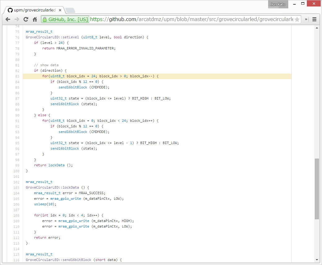
Let me reuse this thread since it’s related to use of this module for another platform - this time, Intel Edison + Grove Shield.
Intel Edison uses libmraa to access its gpio port, so I read the source code of the Arduino library and wrote a mraa-version of it. Given that there’s already a mraa driver for MY9221, coding was straight-forward.
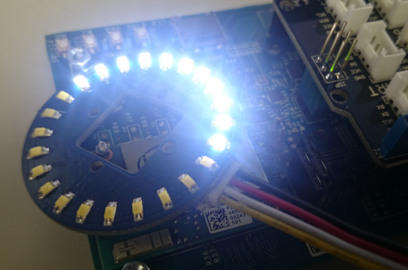
Though, the resulting behavior is not as intended. Only half of the ring gets lightened. It seems like only one of two MY9221 modules is getting the signal. Any thoughts?
I’d like to paste a link to my GitHub repo and the YouTube video executing the code, but it’s not allowed due to the anti-spam mechanism of this forum…
And now I noticed I can upload image files, interesting!
Problem solved! Adding one line (mraa_gpio_use_mmaped) did a trick.
[code] // init clock context
m_clkPinCtx = mraa_gpio_init(dcki);
if (m_clkPinCtx == NULL) {
fprintf(stderr, “Are you sure that pin%d you requested is valid on your platform?”, dcki);
exit(1);
}
mraa_gpio_use_mmaped(m_clkPinCtx, 1); // newly added
// init data context
m_dataPinCtx = mraa_gpio_init(di);
if (m_dataPinCtx == NULL) {
    fprintf(stderr, "Are you sure that pin%d you requested is valid on your platform?", di);
    exit(1);
}
mraa_gpio_use_mmaped(m_dataPinCtx, 1); // newly added[/code]
Default GPIO API for Intel Edison was too slow to send two control commands.
There is a prefined macro/function for the bitmask on every Arduino:
digitalPinToBitMask();
I simplified the code, but did only a rough test on several pins on the MEGA:
(the last 2 lines replaces many lines)
CircularLED::CircularLED( int data,  int clk) {
    _data= data;
    _clk = clk;
    pinMode(_data, OUTPUT);
    pinMode(_clk, OUTPUT);
    PORT_Data = portOutputRegister(digitalPinToPort(_data));
    PORT_Clk = portOutputRegister(digitalPinToPort(_clk));
    // changed to digitalPinToBitMask() to work on MEGA - 5.1.16 NR  maybe works also on UNO
    BIT_Data = digitalPinToBitMask(_data);
    BIT_Clk = digitalPinToBitMask(_clk);
}
Maybe it will help someone, Norbert