Most tiny microcontrollers (including the Xiao) can’t provide a lot of power. So it is common to have an external power supply that runs the power hungry circuit, and provides power to the microcontroller when it is not connected via USB.
From the circuit diagram it looks like there is a diode (D4) blocking current from going from the 5V pin to VBUS, thus meaning it should be fine to have power on the 5V pin while having the USB cable connected.
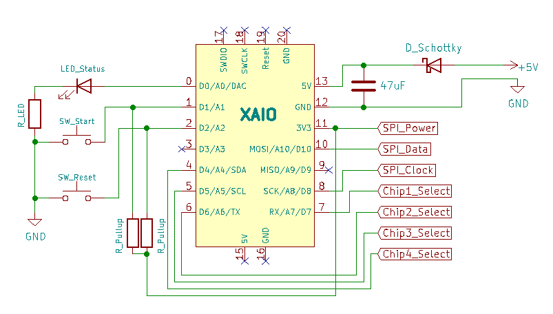
My circuit will have a Schottky Diode on the +5v line to prevent the Xiao from powering the rest of the power hungry circuit during programming.
I haven’t tried it yet because I don’t want to fry the Xiao.
I expect there will be a lot of tweaking with the project, so lots of program updates, and I don’t want to have to pull the Xiao out of the circuit/box each time we need to fiddle with the code.
Just wanted to confirm that I can have power on the 5V pin and USB connected at the same time.
And, if it cannot be done, then I need to adjust the plans (modified data-only USB cable, ZIF socket).
With your diode you should be safe. I have done the same. Without you will power the rest of your circuit from USB, which might be too much load on the USB port. But an standard conform USB port should have not problem with this. It should simply switch off on overload (> 500mA). Unfortunately many USB ports are not standard conform.
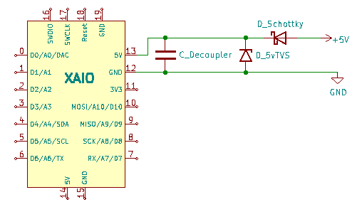
Just one warning, I learned that the XIAO seems to be a bit sensitive to spikes on the 5V line. I have already fried two XIAOs. Now I have a 5V transzorb diode and a big fast cap (10µF X7R) directly at the 5V supply.
Thanks for the input. This will be my first custom PCB, so I’d like to get it right the first time.
The 47uF cap in my circuit above is to decouple any spikes. Is that too high? Was the “10µF X7R” a calculated value, or just happened to be a common “big one” in your parts drawer?
I will definitely add some 5V TVS diodes to my shopping list for the projects using the Xiao (and maybe the other microcontrollers, too).
The cap was just what I had. I took a ceramic because it’s fast. I had the impression that there must have been some fast spike because it happened during switch off (or on).
Be careful with the 5V transzorb, if you supply is a bit high it will be conducting always.
The Xiao uses a XC6206P332MR voltage regulator on the VBUS/5V to bring the power down to 3v3 internally. If I read the data sheets right, it has a max of 6V at the input, and a fixed output of 3.3V (±1%), with max 200mA. I couldn’t make out what the min voltage is before it can no longer put out 3.3V (might be on the datasheet linked above, but it wasn’t obvious to me).
But, knowing how those voltage regulators work, I figure one could run the input voltage at the 5V pin quite a bit lower (4V?) and still get proper power to the microcontrollers inner workings. In my example below (which I will likely be using often) the Schottky diode will drop the initial 5V down to roughly 4.5V, so a 5V TVS after that would likely only be conducting with significant over voltage.
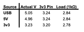
Because I was now curious, I measured the 3v3 pin and a digital high pin with a sample load (1kΩ) when 5v or 3v3 is applied to the 5V pin on the Xiao, or with a USB cable connected. Sadly, I don’t have the means to test if the chip at different voltages (no variable power supply), and if the speed of the chip was affected (no scope).
My program appeared to be working properly on the breadboard with the 3v3 at the 5V pin. So, it looks like you don’t need a particularly low forward voltage Schottky diode.
Again, thanks for the input, and hopefully this info will help me (and others) to avoid damaging their Xiao when programming it in a circuit that uses an external power supply and power hungry devices (i.e. USB and external power connected at the same time).
I guess you should be safe with this configuration. I would advise to place the cap and the transzorb close to the XIAO pins. I know from bad experience that even some few centimeters of traces can be too long to catch any spikes.
One more point when designing with multiple power supplies: There is always the risk that unpowered components gets indirectly powered by others that are powered (one output goes to an unpowered input, drives that chip via the internal protection diodes). If your design allows I would add series resistors to any XIAO pins that might connect to other components that are powered differently.
Usually 1k…4k7 should be enough, but keep in mind that they create a low pass filter with any spurious capacitance.