Hi everyone,
I have been trying to use the CAN Bus Shield V2.0 with an Arduino Uno to send frames to a stepper motor driver that requires CAN Bus.
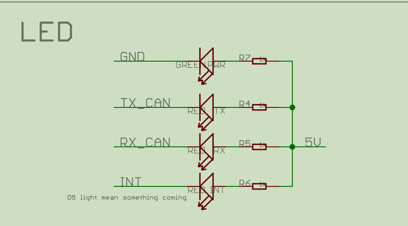
When I open the serial monitor, I see that the shield initialization is successful. The PWR LED is green and is the only LED lighting on the shield, and when I send any command, the Rx and Tx LEDs turn red. The INT LED never lights up.
I tried to look through the documentation and other forums but I cannot find any explanation on what the different status of an LED means. All I found is that the Rx and Tx pins should blink when receiving/sending data, but no explanation about what a red LED means. The Red LEDs will only disappear if I disconnect and reconnect the Arduino’s power. Does anyone know where I can find this information?
Thank you