Hi All,
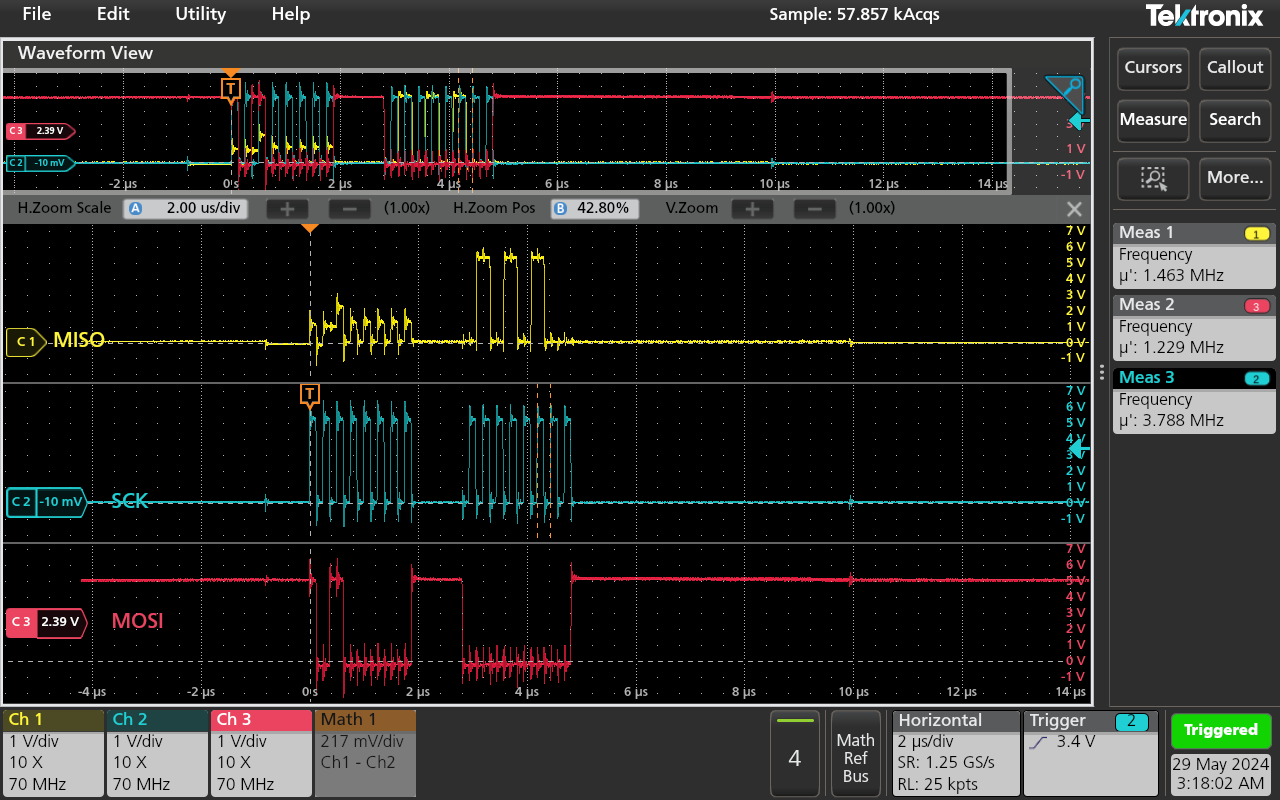
I’m using a CAN-BUS Shield V2.0 with Arduino Uno R3. I have connected the rear jumpers for CS_CAN = pin10, and SPI configured for SPI_B (pins 13, 12, 11 are SCK, MISO, MOSI). I am using the example code for the most part, with the exception of manually adjusting specific bytes of my extended frame CAN message. While the system is sending (and receiving) CAN Messages (I have another identical system receiving and printing CAN messages), I am looking at the SPI signals on an oscilloscope and see a strange MISO signal. It looks like some bits are being partly driven, to 1, 2, or 3V instead of the full 5V logic signal.
Why is the MISO signal giving me partial logic signals?
// demo: CAN-BUS Shield, send data
// [email protected]


#include <SPI.h>

#define CAN_2515
// #define CAN_2518FD

// Set SPI CS Pin according to your hardware

#if defined(SEEED_WIO_TERMINAL) && defined(CAN_2518FD)
// For Wio Terminal w/ MCP2518FD RPi Hat:
// Channel 0 SPI_CS Pin: BCM 8
// Channel 1 SPI_CS Pin: BCM 7
// Interupt Pin: BCM25
const int SPI_CS_PIN  = BCM8;
const int CAN_INT_PIN = BCM25;
#else

// For Arduino MCP2515 Hat:
// the cs pin of the version after v1.1 is default to D9
// v0.9b and v1.0 is default D10
const int SPI_CS_PIN = 10;
const int CAN_INT_PIN = 2;
#endif


#ifdef CAN_2518FD
#include "mcp2518fd_can.h"
mcp2518fd CAN(SPI_CS_PIN); // Set CS pin
#endif

#ifdef CAN_2515
#include "mcp2515_can.h"
mcp2515_can CAN(SPI_CS_PIN); // Set CS pin
#endif

void setup() {
    SERIAL_PORT_MONITOR.begin(115200);
    while(!Serial){};

    while (CAN_OK != CAN.begin(CAN_250KBPS)) {             // init can bus : baudrate = 500k
        SERIAL_PORT_MONITOR.println("CAN init fail, retry...");
        delay(100);
    }
    SERIAL_PORT_MONITOR.println("CAN init ok!");
}

unsigned char stmp[8] = {0, 0, 0, 0, 0, 0, 0, 0};
void loop() {
    // send data:  id = 0x00, standrad frame, data len = 8, stmp: data buf
    stmp[7] = stmp[7] + 1;
    if (stmp[7] == 100) {
        stmp[7] = 0;
        stmp[6] = stmp[6] + 1;

        if (stmp[6] == 100) {
            stmp[6] = 0;
            stmp[5] = stmp[5] + 1;
        }
    }

    CAN.sendMsgBuf(0x00, 0, 8, stmp);
    delay(100);                       // send data per 100ms
    SERIAL_PORT_MONITOR.println("CAN BUS sendMsgBuf ok!");
}

// END FILE
Edit 1: update category
Edit 2: include code block
Hi there,
So where are the buss resistors? what are the value? I don’t think the uno has them ?
HTH
GL:-) PJ
and did you , per wiki?
“When you use more than two CAN Bus Shield in one net, you should take the impedance into consideration. You should either cut P1 in the PCB with a knife, or just remove R3 on the PCB.” ?
Thanks for your questions PJ!
The CAN BUS resistors are on-board the CAN-BUS Shield at 120 ohms per shield. Is this what you were referring to by “buss resistors”?
And I did not cut P1/remove R3 because the issue was replicated both with and without the second system on the bus receiving the CAN messages. Is it still necessary to do with only the one shield on the system?
Hi there,
Yes, Ok I see the resistors on the schematic on the wiki for the can buss, Strange behavior for sure, Looks like the pull ups maybe for the SPI is weak or wrong value? Try adding a pull up in parallel. see if the signal cleans up, definitely looks squirrely. It does clean up though you say? What’s the SPI clock speed?
HTH
GL  PJ
PJ

What does MISOB look like? I see the board has two A & B
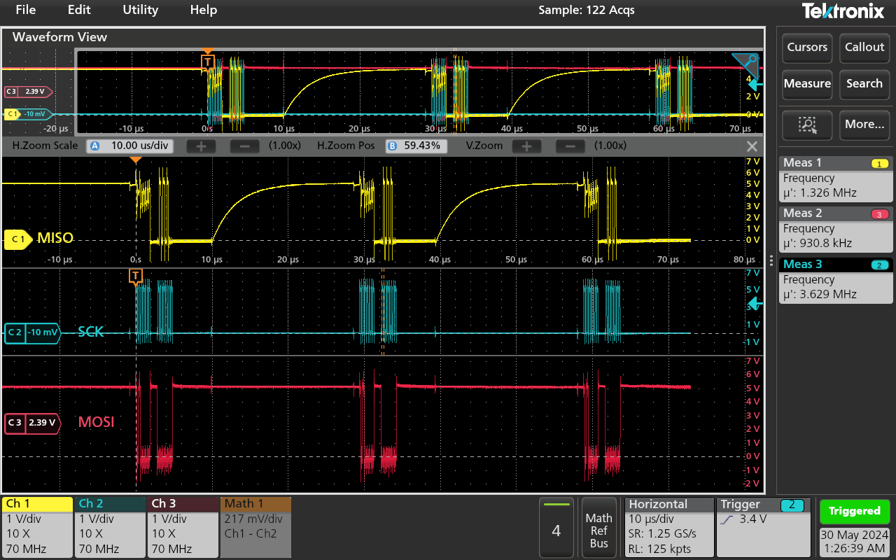
I attempted to put a 51k ohm pull up and pull down resistor on the MISO pin (MISO to VDD/GND). The pull up will keep the signal hovering at 5V, but I am still encountering the strange “half driven” signal. Also, I’m getting a sort of charging waveform following that dataset. Screenshot attached below. My SCK is running at 4MHz. I’ve also tried this on another arduino/can hat system and seen the same results…
MISO A and MISO B look the same unfortunately.
Unfortunately it does not change if connected/disconnected to the can bus.
I was talking to a coworker and he was convinced that it was just noise, but I’m hesitant to believe that due to the “multiple levels” of the signal… Could my scope just be picking up noise from the adjacent SCK pin?
I think this specific waveform is “noise” from the adjacent MOSI and SCK signals.
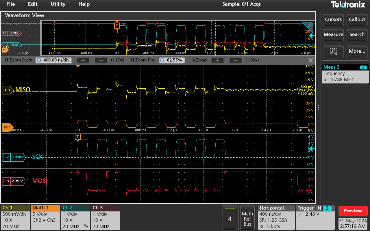
I disconnected my MISO pins completely and had my scope probes still connected, and noticed I was still getting some waveforms. I then performed a math function on my SCK and MOSI waveforms, zoomed it out a lot, and saw that my noise seemed to mirror this signal almost exactly. On the image below you can see the topmost waveform where the orange and yellow signals are almost completely overlapped. The individual waveforms are below that.
I’m still getting some weird behavior on the MISO line when I have another system connected but I will open another thread after some more debugging. Thanks for your support PJ!
I have often encountered this phenomenon.
This is a common phenomenon when the GND of the probe is not properly connected. How and where are the four GND clips connected?
Hi msfujino,
My system was an arduino with the CAN hat sitting on top of it. From there I have a breadboard which is receiving the 5V and GND pins to the rails which will power an ADC on the side (unused at the moment for this test). My 3 scope probes are connected to a jumper coming from the ground rail (multimeter measured 0.3 ohms between arduino and jumper) on the breadboard via alligator clips (Tektronix TPP0200 probes).
I am probing the signals coming from the arduino to spaces on the breadboard, each signal getting their own row.
If there is a single GND wire connecting the breadboard to the Arduino/CAN, it could have a large common impedance. What happens if the GND clip of each channel is connected independently to the GND pin of the Arduino/CAN?
Unfortunately the same thing happens, there’s no change.
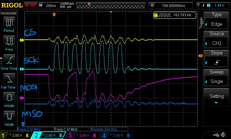
This is the waveform I observed for my test. Each signal is pulled out with a 5cm lead for observation. Each signal interferes with each other due to the common impedance of GND. (The bandwidth of the oscilloscope is 100 MHz, so the waveforms are not sharp.)
Unfortunately, it seems that this is not the phenomenon you are encountering.