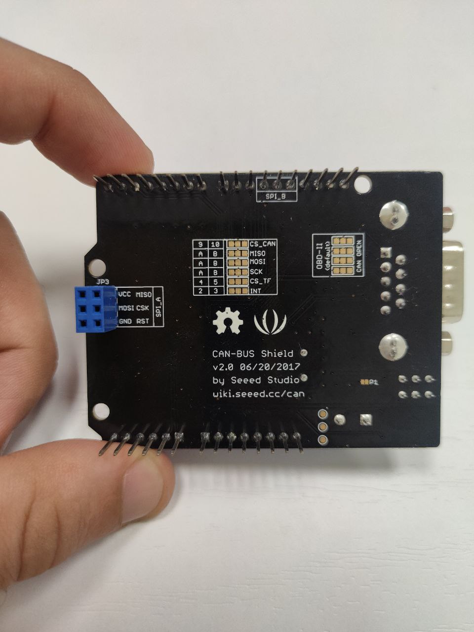
I want to exchange data between CAN BUS ANALYZER and an Arduino Uno connected to the CAN BUS SHIELD V2.0.
I uploaded the following example code on Arduino from the Seed_Arduino_CAN-master library
send.ino:
"// demo: CAN-BUS Shield, send data
// [email protected]
#include <SPI.h>
#define CAN_2515
// #define CAN_2518FD
// Set SPI CS Pin according to your hardware
#if defined(SEEED_WIO_TERMINAL) && defined(CAN_2518FD)
// For Wio Terminal w/ MCP2518FD RPi Hat:
// Channel 0 SPI_CS Pin: BCM 8
// Channel 1 SPI_CS Pin: BCM 7
// Interupt Pin: BCM25
const int SPI_CS_PIN = BCM8;
const int CAN_INT_PIN = BCM25;
#else
// For Arduino MCP2515 Hat:
// the cs pin of the version after v1.1 is default to D9
// v0.9b and v1.0 is default D10
const int SPI_CS_PIN = 9;
const int CAN_INT_PIN = 2;
#endif
#ifdef CAN_2518FD
#include “mcp2518fd_can.h”
mcp2518fd CAN(SPI_CS_PIN); // Set CS pin
#endif
#ifdef CAN_2515
#include “mcp2515_can.h”
mcp2515_can CAN(SPI_CS_PIN); // Set CS pin
#endif
void setup() {
SERIAL_PORT_MONITOR.begin(115200);
while(!Serial){};
while (CAN_OK != CAN.begin(CAN_500KBPS)) {             // init can bus : baudrate = 500k
    SERIAL_PORT_MONITOR.println("CAN init fail, retry...");
    delay(100);
}
SERIAL_PORT_MONITOR.println("CAN init ok!");
}
unsigned char stmp[8] = {0, 0, 0, 0, 0, 0, 0, 0};
void loop() {
// send data: id = 0x00, standrad frame, data len = 8, stmp: data buf
stmp[7] = stmp[7] + 1;
if (stmp[7] == 100) {
stmp[7] = 0;
stmp[6] = stmp[6] + 1;
    if (stmp[6] == 100) {
        stmp[6] = 0;
        stmp[5] = stmp[5] + 1;
    }
}

CAN.MCP_CAN::sendMsgBuf(0x00, 0, 8, stmp);
delay(100);                       // send data per 100ms
SERIAL_PORT_MONITOR.println("CAN BUS sendMsgBuf ok!");
}
// END FILE"
The system is not working since CAN BUS ANALYZER is not receiving any message.
I’m using a CAN BUS ANALYZER by Microchip DB9-usb, I added a 120 ohm resistor to the shield but the Tx and Rx leds on the shield are not blinking, but are instead constantly on.
Does anyone have the same problem? How can I fix it?
Thank you in advance