Hi all, I made a super simple pcb to power a motor with a few switches and I intended to power this with an 18650 in a battery clip. Because the built-in charger doesn’t have a low voltage cutoff (which I really really wish it did!) I thought to get a BMS. I got this one: https://www.amazon.com/gp/product/B07KSPYMJ2
There’s no datasheet but the description says it has to be activated by hooking it to a charger. Great, the Xiao has a built-in charger! The battery is probably too big to charge with 100mA but I thought a quick touch to the usbc and it would go, but it doesn’t. So it seems the device needs more power to activate the BMS. This is a super annoying situation that I’ve been going in circles on. (some commenters said you could just short B- and P- but that also didn’t work, and that you needed 9V to activate, which also didn’t activate, and also seems to have fried the Xiao, even though I think the battery charger should sustain 30V according to its datasheet.)
Is anyone aware of a little 1S BMS that doesn’t require activation? I don’t even understand what charging has to do with discharging, or why that activation is considered a useful feature. Second question, can one buy just an overdischarge protection circuit? I’m going to be charging this battery in a proper charger so all I really care about is not damaging the battery from over discharge.
Hi there,
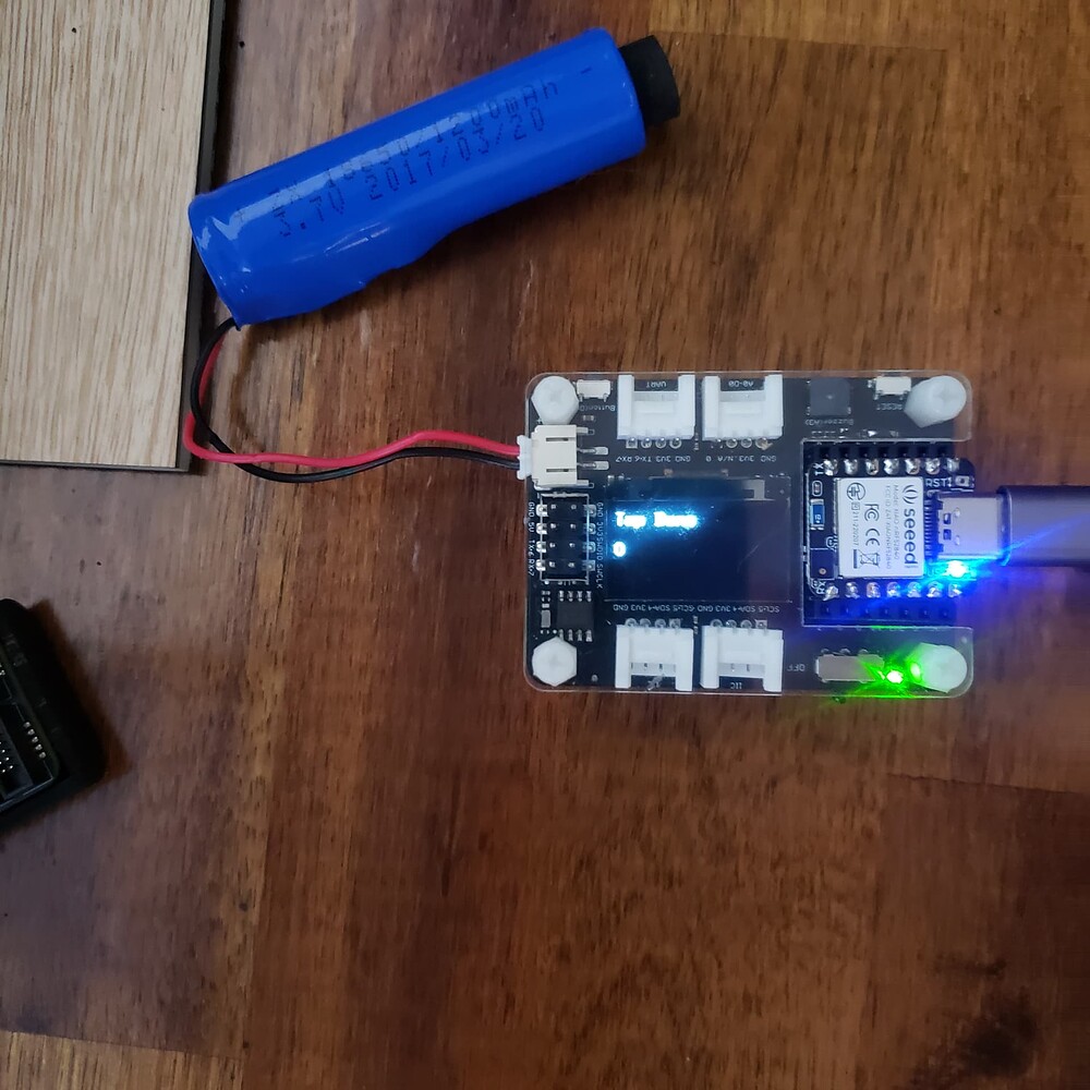
WoW, That’s sound like malarkey, I have used an 18650 for two years with a Xiao Nrf52840 BLE and The Sense variant. Depending on The BSP you use It is possible to monitor the Battery Voltage, USB in or NOT? Change the Charge Current from 100 ma. to 50ma also.
Why would anyone connect 9V to a 3.3 v max device? Smoke Test is all you’ll Get
Works with the Xiao , works with the Dev board and Also works with the Grove Expansion board with the Extra Flash installed. If you look at the schematics and Data-Sheet of theses you 'll see the trend with the PMIC’s
HTH
GL PJ
PS, if you try and use a USB power bank Eliminates the battery soldering(I use one with Solar) Some will shut off because when the Xiao is ASleep draws so little current it thinks it’s Off. and powers down.
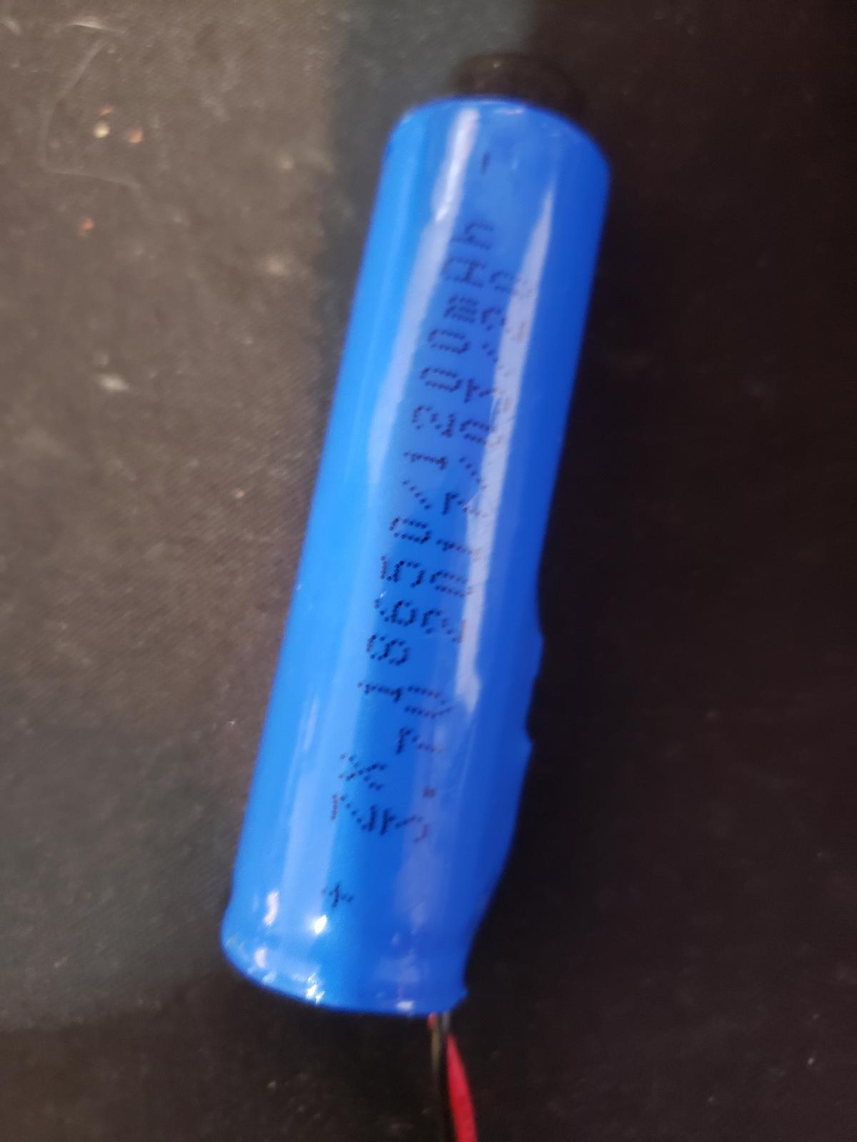
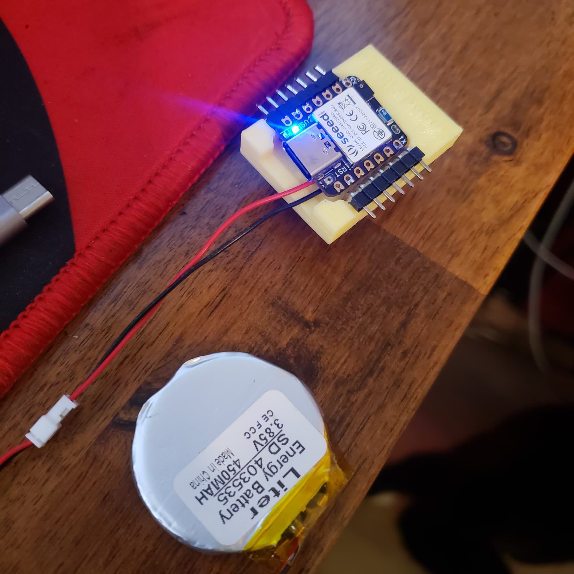
I can see from your picture that your battery already has a bms under the shrinkwrap, that’s what I’m trying to buy one of that either doesn’t have an activation routine or is activated by the Xiao built-in charger.
The battery clip I have is too small to fit a protected battery (generally they’re longer) and that’s on purpose because it needs to fit in a constrained area. So I have placed a small BMS on the PCB but I fear I have an inappropriate one.
You’re right that 9v is risky/dumb, but I did look at the schematic and checked the data sheet of the TI charge controller, and it’s 30v absolute max. But, sadly I think the voltage sense connection to pin 14 probably allowed the smoke weasel to wriggle in there. But I suspected if I couldn’t get the BMS activated then the whole board was wasted because of the dumb battery pads on the bottom of the XIAO (SEEED, PLEASE MAKE THEM CASTELATED PINS!). I probably close to cooked the XIAO getting it to stick to the PCB battery pads in the first place, pulling it off was not going to be fun.
I have extras of all of these things, but just hoping someone could show me the way with the BMS, probably need a new footprint. On the other hand, do you have a link for the battery you have? Most protected 1S batteries seem to have the protection incorporated in a button top, which makes them longer. Maybe yours has a flat top with the BMS already on there. Can’t quite tell from the pics.
Thanks for that reference. I messaged the provider of my battery and they said it is protected, but I’ll need to test that I guess because it’s the shorter style and doesn’t have any visible bms shrink wrapped on. Soldering the battery pads to wire is easy but it is mechanically unstable. I have had them come off multiple times. In this case I am soldering blind to a pcb but I didn’t have solder paste, so I heated the back of the pcb and managed to get it done. But the regular solder reflow temp is much too hot for that method, especially coming off. I have some paste now that will work much better, but really, they just need to put the charger pins on castellated pads. In every project I have done with the Xiao boards, the battery is the hardest part and the weakest link despite that the included charger at this size is the whole reason to choose this board! This project will use the same battery to power a geared motor and drive a strip of leds, so I can’t use the little lipos.
Hi there,
Agreed, It’s why I use a PC board and the Oval Through holes (plated & filled) Tech in the PCB on here.
Then a JST or PST connectors for the battery. I can Pull AMPS (tested) thru the connection.
Good Low melt Solder Paste is the truth for this type of Rodeo
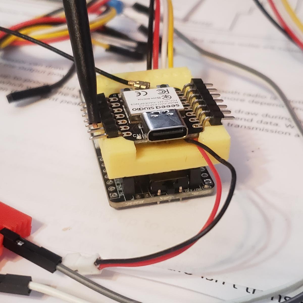
You got a lot going on right there, SO a proper plan for the power distribution, Ground plane keep out area for the BLE is key ,even a little noise will hamper any kind of radio range , So FYI.
HTH
GL PJ
One board has JST to a Solenoid and a darlington pair of FET’s triggered by the Xiao IO and it’s important to decouple the noise when switching such small signal levels.