Hi all!
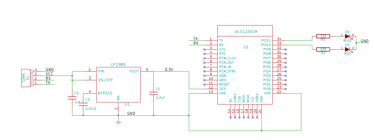
I’ve purchased a WLS123A1M Serial port bluetooth module. I want to use it with my Arduino and for this I decided to make some basic wiring to get something like GROVE module. Unfortunately there are no schematics of GROVE bluetooth module available so I made basic schematic myself and just want to ask if everything is correct. My main doubts concern the RESET pin of WLS123A1M: is it OK to leave it unconnected? The schematics are in the file attached.
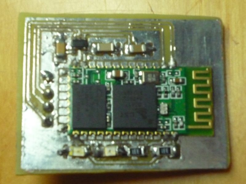
Well, nobody cared to reply, so I tried it out and it worked. Used sample sketch from seedstudio wiki page on Grove Serial bluetooth. You can use 5.5V input voltage (or even higher) thanks to voltage regulator. The photo of my board is attached.
I’m having trouble just writing the AT-commands to the Bluetooth module. I can write them just fine, I just get some very strange output back. After having send a couple of commands, they just start being returned.
If i send ‘\r\n+STWMOD=0\r\n’ I get some gibberish back. Then, I try sending it again, which returns gibberish + ‘+STWMOD=0\r\n’. Then i try sending the same command again i get something like gibberish + ‘+STWMOD=0\r\n+STWMOD=0\r\n’. If i try again, i get an even longer reply. I’m wondering if anyone else has experiences this, and know how to fix it?
My current course of action is trying to scale the Uart signal from 5 to 3.3, to better suite the Bluetooth circuit. But to the best of my knowledge that shouldn’t really do much.
Damn, this is causing me a lot more trouble than i would have thought.
Well, yes, actually I did. I mentioned above, that I used a sample Arduino sketch for GROVE Bluetooth which is available on seedstudio wiki at seeedstudio.com/wiki/Grove_- … _Bluetooth. I don’t know it this counts for you but i was able to see the response on my PC via the common bluetooth usb dongle. Unfortunately i didn’t have time yet to write my own program and test it out but it seems that it works somehow.
hi, im using this on my stm32. But I have some understanding problems.
I connected it same way like you with 3,3v VCC.
I init the USART2 with 38400 baud , rts, cts.
then my code (it blinks one time when parameter got sent, for debbuging):
[code] /
Init BT */
/*here i need the printf and “cout” function, to check the echo replying from the BT over USART2 */
IMU_Led1_Toggle();
send_string(“\r\n+STWMOD=0\r\n”); IMU_Led1_Toggle();
send_string(“\r\n+STBD=38400\r\n”); IMU_Led1_Toggle();
send_string(“\r\n+STNA=IMU\r\n”); IMU_Led1_Toggle();
send_string(“\r\n+STAUTO=0\r\n”); IMU_Led1_Toggle();
send_string(“\r\n+STOAUT=1\r\n”); IMU_Led1_Toggle();
send_string(“\r\n+STPIN=0000\r\n”); IMU_Led1_Toggle();
send_string(“\r\n+INQ=0\r\n”); IMU_Led1_Toggle();
Delay(200);
[/code]
The pairing LED flashes 2 times in 1 second.
But I cannot find the module from my internal BT in my Laptop, I find nothing. → WHY?
Isn’t the device in discovery mode when it got power?
Sadly I can’t debug the USART2 because I didn’t finshed the printf function for my debugger yet, for reading the echos of the module.
Is my initialisation ok?
I want that the WLS123A1M for transmitting data to my PC.