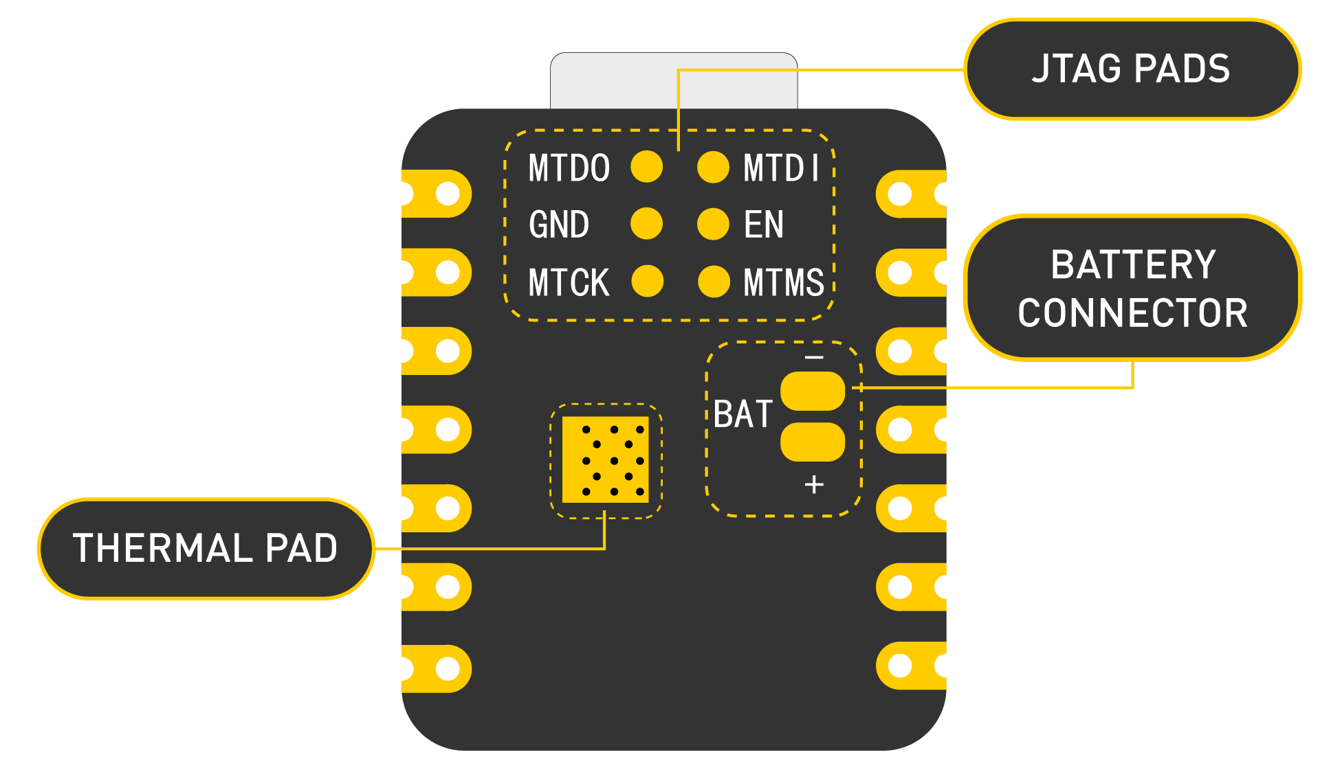
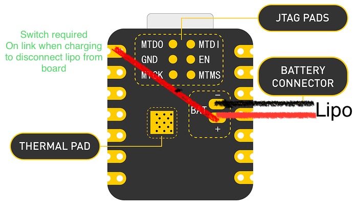
The battery is connected via the pads on the rear of the board… as mentioned the only way to power the board is to jump the positive connection to the 5v connection on the board with a bridging wire.
We did a test a while ago, using a simple Blink program, and the XIAO ESP32C3 worked fine with only the battery connected, and the GPIO was able to output a jump in voltage. However, it should be reminded that the 5V supply pins will not output 5V when the battery is powered, which is the design of the hardware.
I believe XIAO has a built-in PMOS switch circuit that switches between battery voltage and USB 5V.
Disconnecting USB should switch to battery, but I suspect it is not working properly.
Nope the boards i have are faulty - others can run straight off the battery terminals - where as the ones i have need a wire soldering from the battery + to the 5v pin on the board.
I have 2 of these seeed xiao esp32c3 boards that I plan to use for a project and they need to be powered by rechargeable 3.7v batteries. I am having the same issue as you, neither board will run off the battery without a bridge or work around, which sucks because I really need it to work.
I have also been working with a TTGO Display S3 ESP32S and to enable the battery you have to set the GPIO pin 15 to output and High and then the board will run off the Battery, i do wonder if this is the same with the XIAO but really need the Devs to confirm the workings of the board in more detail
Please see the link below, there may still be a schematic for XIAO_BLE. I checked before and the power supply circuit was the same as the XIAO_ESP32C circuit.