Batch differences in product. Bootloader changes and code trouple

Hi folk,
I’m seeing a strange behaviour as we start to scale up our manufacturing using a Xiao nrf52840 sense.

Basically I have two batches of devices, one of which works and the other has problems.

The only difference I can see in the Arduino IED is that the devices have a different board name and PID

The working batch has a board name of:
Seeed XIAO BLE - nrf52840 and a PID of 0x8045.

The non working batch has a board name of:
Seeed XIAO nrf52840 and a PID of 0x8044.

If I load the .DFU file from the working batch to the non working batch, these details are updated, but my code still fails to run.

Is there anything else that could be different between the batches? To be clear, I can still run example code on the ‘bad’ batch, but not my code. My code works fine on one batch. on the 'bad batch I find I have to enter DFU mode quite often as uploads fail. Is there anything else I can flash to update my bad batch? The problem I have too is that the boards are SMD on a custom board and don’t expose the rear pins…

Any thoughts would really help me out. I’m really pulling my hair out!

The two batches may have different bootloader versions.

Hi there,

WoW, bad day on that for sure… Open one in Nrf Connect for Desktop, It should display the bootloader version.

HTH
GL :slight_smile: PJ :v:

Thanks for getting back to me both,

I’m guessing I’d need to connect a debugger via the rear pins to read the bootloader version?
Can it be done via USB and if so, can I update the boot loader without board rear access?

Thanks again!
James

Hi there,

So there is and it’s not available AFAIK…
With NORDIC DFU you can use this command nrfutil.exe with some switches, for example
to list the device connected (I have a Xiao nRF52840 Sense ) i get this output
It is on COM5 (serial port in DFU/Bootloader mode) I see the F-drive as well.

C:\Users\Dude>nrfutil device list
539FCE879A499CF3
product         XIAO nRF52840 Sense
ports           COM5
traits          serialPorts, usb

if it were a NORDIC bootloader the next line would be displayed with

serial_number: 539FCE879A499CF3
deviceFamily:  nRF52
deviceVersion: nRF52840_XXXX
ramSize:       ...
romSize:       ...
bootloaderVersion: ...

But because it’s an adafruit/half a boot , it’s not supported.
You could also update the Bootloader without touching the code to using the addresses and nrfUtil as well(advanced class) :sunglasses:

don’t give up There may be a method with Adafruit-Nrfutil… they have a bastardized version.
Seeed should get a better one from nordic…LOL

HTH
GL :slight_smile: PJ :v:

I’ll test it some more, but can you just check date codes or desolder one and check maybe your only option.

Hi there,
Going back and re-reading this, First are You sure(imprint sure) they are the Sense versions?
LMK.
captain obvious :grin: :ok_hand:

You could also try just updating the bootloader and see if it fixes it.
It’s a long shot but load up a bluefruit example,
something like this recent master piece; :yum:

#include <Wire.h>
#include <SPI.h>
#include <bluefruit.h>

//***********************************************************************************************************
#define FAST                    // compiler option : parameters setting for fast transmission
                                // if default setting, comment out
#define MAX_PACKET  200         // maximum number of data packets allowed by FIFO
#define FIFO_SIZE DATA_NUM * MAX_PACKET  // FIFO size, push and pop on a packet-by-packet basis
#ifdef FAST
  #define DATA_NUM  244         // number of bytes in data packet
#else
  #define DATA_NUM  20          // number of bytes in data packet
#endif
//***********************************************************************************************************

union unionData {               // Union for data type conversion
  uint32_t  dataBuff32[DATA_NUM/4];
  uint8_t   dataBuff8[DATA_NUM];
};
union unionData ud; 

uint16_t conn;                  // connect handle
bool notifyFlag = false;        // set by notify callback
bool connectedFlag = false;     // set by connect callback

// Custom Service and Characteristic
// 55c40000-8682-4dd1-be0c-40588193b485 for example
#define customService_UUID(val) (const uint8_t[]) { \
    0x85, 0xB4, 0x93, 0x81, 0x58, 0x40, 0x0C, 0xBE, \
    0xD1, 0x4D, (uint8_t)(val & 0xff), (uint8_t)(val >> 8), 0x00, 0x00, 0xC4, 0x55 }

BLEClientService        customService       (customService_UUID(0x0000));
BLEClientCharacteristic customCharacteristic  (customService_UUID(0x0030));

unsigned long startTime = 0;
unsigned long packetCount = 0;
unsigned long totalDataReceived = 0; // in bytes
const unsigned long interval = 2000; // 10 seconds

void setup() {
    delay(2000);
    Serial.begin(115200);
    delay(2000);

    // LED initialization
    pinMode(LED_RED, OUTPUT);
    pinMode(LED_GREEN, OUTPUT);
    pinMode(LED_BLUE, OUTPUT);

    Serial.println("------ Central Board ------");
    Serial.println("Start Initialization");
    
    // Initialization of Bluefruit
    Bluefruit.configCentralBandwidth(BANDWIDTH_MAX);  
    Bluefruit.begin(0, 1);
    Bluefruit.setName("XIAO BLE Central");

    // Custom Service Settings
    customService.begin();
    customCharacteristic.setNotifyCallback(data_notify_callback);
    customCharacteristic.begin();

    // Blue LED blinking interval setting
    Bluefruit.setConnLedInterval(100);

    // Callbacks
    Bluefruit.Central.setDisconnectCallback(disconnect_callback);
    Bluefruit.Central.setConnectCallback(connect_callback);
    
    // Scanner settings
    Bluefruit.Scanner.setRxCallback(scan_callback);
    Bluefruit.Scanner.restartOnDisconnect(true);
    Bluefruit.Scanner.setIntervalMS(100, 50);    
    Bluefruit.Scanner.filterUuid(customService.uuid);
    Bluefruit.Scanner.useActiveScan(false);
    Bluefruit.Scanner.start(0);                  

    Serial.println("End of initialization");
    startTime = millis();
}

void loop() {
    unsigned long currentTime = millis();

    if (currentTime - startTime >= interval) {
        // Calculate the sampling rate (packets per second)
        float samplingRate = (float)packetCount / (interval / 1000.0);

        // Calculate the bit rate (bits per second)
        float bitRate = (totalDataReceived * 8) / (interval / 1000.0);

        Serial.print("Sampling Rate: ");
        Serial.print(samplingRate);
        Serial.println(" packets/second");

        Serial.print("Bit Rate: ");
        Serial.print(bitRate);
        Serial.println(" bits/second");

        // Reset counters and timer
        packetCount = 0;
        totalDataReceived = 0;
        startTime = millis();
    }
}

//*************************************************************************************************************************************************************************************
// THE CONNECTION IS ESTABLISHED 
//*************************************************************************************************************************************************************************************
// FUNCTIONS FOR CONNECTION with the peripheral 
void scan_callback(ble_gap_evt_adv_report_t* report)
{
  Bluefruit.Central.connect(report);
}

void connect_callback(uint16_t conn_handle){
    conn = conn_handle;
    connectedFlag = false;
    if (!customService.discover(conn_handle))
    {
        Serial.println("【connect_callback】 Service not found, disconnecting!");
        Bluefruit.disconnect(conn_handle);
        return;
    }
    if (!customCharacteristic.discover())
    {
        Serial.println("【connect_callback】 Characteristic not found, disconnecting!");
        Bluefruit.disconnect(conn_handle);
        return;
    }

    // After discovering the characteristic, enable notifications
    if (!customCharacteristic.enableNotify()) {
        Serial.println("Failed to enable notifications");
    } else {
        Serial.println("Notifications enabled");
    }

    connectedFlag = true;
    Serial.println("【connect_callback】connected");
}

void disconnect_callback(uint16_t conn_handle, uint8_t reason){
  (void) conn_handle;
  (void) reason;

  Serial.print("【disconnect_callback】 Disconnected, reason = 0x");
  Serial.println(reason, HEX);
  connectedFlag = false;
}
//*************************************************************************************************************************************************************************************
//*************************************************************************************************************************************************************************************

// Callback when new data is available on the characteristic
void data_notify_callback(BLEClientCharacteristic* chr, uint8_t* data, uint16_t len) {
    // Count the packets and accumulate the total data received
    packetCount++;
    totalDataReceived += len;
    
    // Process the received data
    sendDataThroughSerial((char*)data, len);
}

// Function to send data through the serial port
void sendDataThroughSerial(char* data, uint16_t len) {
    //Serial.print(data);  // This sends the string up to the null terminator
    //Serial.println();
}

Go to the tools menu after connecting your Xiao in Bootloader mode, set the correct com port and query the board type if it comes back ok then choose the the programmer "Bootloader DFU for bluefruit nRF52 " then hit “Burn Bootloader”
you should see it program the bootloader. disconnect when it’s done and reset see what happens…
YOLO
:face_with_hand_over_mouth: :ok_hand:

HTH
GL :slight_smile: PJ :v:

So one other small item on this,
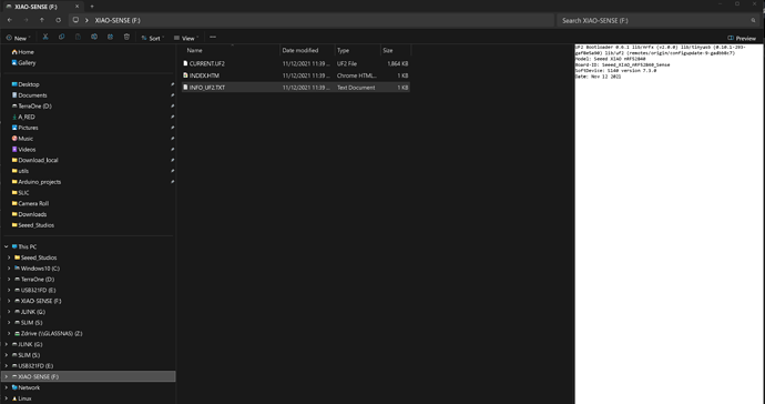
Are you able to get into Bootloader mode on these units? If so the contents of the
info_UF2.txt file on the drive that appears has the info in it.

i.e…

UF2 Bootloader 0.6.1 lib/nrfx (v2.0.0) lib/tinyusb (0.10.1-293-gaf8e5a90) lib/uf2 (remotes/origin/configupdate-9-gadbb8c7)
Model: Seeed XIAO nRF52840
Board-ID: Seeed_XIAO_nRF52840_Sense
SoftDevice: S140 version 7.3.0
Date: Nov 12 2021

Have a look if so, are they the same?
HTH
GL :slight_smile: PJ :v:

Hi PJ,
Really amazing help, I do appreciate it immensely.

To answer some of your questions, I’m sure I’m trying to use Sense units. I guess the question is, how do I know? I mean, they were supplied as sense units and have the MEMS microphone visible and I can read from the Accelerometer, but is there a separate/different bootloader between the versions or is it just extra hardware populated?

I tried and was successful updating the bootloader using you amazing example, worked really well but no change.

I am able to get into the bootloader and the UF2.txt files are identical to the example you provided on both batches.

Today, I’ve been trying to figure out a work around for the actual problem of my code not working on the ‘bad’ batch and have narrowed it down to an interesting observation at least…

It’s something to do with the external flash that I’m using.

On the ‘working units’, I define the FLASH connections like this:

SPIFlash_Device_t const P25Q16H{
  .total_size = (1UL << 21),  // 2MiB
  .start_up_time_us = 10000,  // Don't know where to find that value
  .manufacturer_id = 0x85,
  .memory_type = 0x60,
  .capacity = 0x15,
  .max_clock_speed_mhz = 55,
  .quad_enable_bit_mask = 0x02,      // Datasheet p. 27
  .has_sector_protection = 1,        // Datasheet p. 27
  .supports_fast_read = 1,           // Datasheet p. 29
  .supports_qspi = 1,                // Obviously
  .supports_qspi_writes = 1,         // Datasheet p. 41
  .write_status_register_split = 1,  // Datasheet p. 28
  .single_status_byte = 0,           // 2 bytes
  .is_fram = 0,                      // Flash Memory
};

Adafruit_FlashTransport_QSPI flashTransport;
Adafruit_SPIFlash flash(&flashTransport);

And I can read/write the 2MB flash, erase it etc.

On the ‘bad’ units, I can call flash.erasechip() but it doesn’t seem to work (although doesn’t error). The FLASH is filled with 0x88. (working erases to 0xFF).

I can get the ‘bad’ units FLASH working using (maybe one of your examples?) this code:

SPIFlash_Device_t const P25Q16H{
  .total_size = (1UL << 21),  // 2MiB
  .start_up_time_us = 10000,  // Don't know where to find that value
  .manufacturer_id = 0x85,
  .memory_type = 0x60,
  .capacity = 0x15,
  .max_clock_speed_mhz = 55,
  .quad_enable_bit_mask = 0x02,      // Datasheet p. 27
  .has_sector_protection = 1,        // Datasheet p. 27
  .supports_fast_read = 1,           // Datasheet p. 29
  .supports_qspi = 1,                // Obviously
  .supports_qspi_writes = 1,         // Datasheet p. 41
  .write_status_register_split = 1,  // Datasheet p. 28
  .single_status_byte = 0,           // 2 bytes
  .is_fram = 0,                      // Flash Memory
};
SPIClass SPI_2(NRF_SPIM0, PIN_QSPI_IO1, PIN_QSPI_SCK, PIN_QSPI_IO0);  // Onboard QSPI Flash chip
Adafruit_FlashTransport_SPI flashTransport(PIN_QSPI_CS, SPI_2);      // CS for QSPI Flash
Adafruit_SPIFlash flash(&flashTransport);

The only difference is the definition of the SPI pins etc. While I can now get the FLASH working on the ‘bad’ units, I’m having incompatibilities with my other libraries such as the sparkfun MCP9600 thermocouple that I’m using which is strange as this is an I2C device and shouldn’t conflict with the SPI of the FLASH.

Quite a frustrating challenge and as both batches were purchased a couple of weeks apart, I’m concerned long term. I think I need to get a workaround for both ‘versions’ and suspect that if I can get the thermocouple library working with the FLASH SPI definitions I might be in a good spot although I’m struggling to see the interdependency.

Really appreciate your help again!
James
1 Like

Hi there

James,
Are you able to load the FLASH self-test examples , does it report back same on both batches.(I used for the Grove expansion board external flash a while back Demo with code) I would try that and post up the resulted serial output… Also Are you using the Uf2 drag and drop files ? Would be easy (make your code a Uf2 drag and drop file)
Try the RGB LED test one I have posted, (unzip) drag and drop on the Xiao. wait a few seconds does the LED blink 3 colors, YES then Reload your code and try it again, do that on both batches.
LMK if anything changes, You’ll figure it out stay at it. :+1:

HTH
GL :slight_smile: PJ :v:

Thanks again PJ,

I have a work around!

I’m using NRF_SPIM2 rather than NRF_SPIM0 now and everything seems to hold up. Basically it seems like I had a conflict with one of my other libraries but only on one batch of boards… This is extremely strange and I’d love to get to the bottom of it, but for now I’m at least working. As I get new batches in, my plan is to test before assembly. And I’ll also be breaking out the debugging pins;)

At the moment I’m loading code via the Arduino IDE. Should I be using UF2 D&D? I’ve not done this yet, I’ll have to suss it out.

1 Like

May be somewhat related, but I’m having flash issues. I was hoping someone could try to following code on a NRF52840 sense and report. Basically I’m only able to write around 64 values and then the flash fails to write. 64 seems awfully co-incidental, but I can’t see where the error is and sometimes after a reset will count much higher.


#include "Adafruit_SPIFlash.h"
 #include "flash_devices.h"


uint32_t currentAddress = 0; // Initialize the starting address

// Memory configuration
const uint32_t flashSize = 2097152;  // 2 MB
const uint32_t blockSize = 4096;     // Block size in bytes
const uint16_t chunkSize = 200;      // Size of each read chunk in bytes (may need to be smaller?) divisible by data size (6)
// Buffer for sending data
uint8_t buffer[chunkSize];  //Store the buffer for chunk.
uint32_t writeAddress = 8;  // Current write address in flash memory (write to memory location 6 after the longinteger at 0 using 0,1,2,3 bytes to store the pointer)
// Memory Definition as described in the P25Q16H datasheet.
SPIFlash_Device_t const P25Q16H{
  .total_size = (1UL << 21),  // 2MiB
  .start_up_time_us = 10000,  // Don't know where to find that value

  .manufacturer_id = 0x85,
  .memory_type = 0x60,
  .capacity = 0x15,

  .max_clock_speed_mhz = 55,
  .quad_enable_bit_mask = 0x02,      // Datasheet p. 27
  .has_sector_protection = 1,        // Datasheet p. 27
  .supports_fast_read = 1,           // Datasheet p. 29
  .supports_qspi = 1,                // Obviously
  .supports_qspi_writes = 1,         // Datasheet p. 41
  .write_status_register_split = 1,  // Datasheet p. 28
  .single_status_byte = 0,           // 2 bytes
  .is_fram = 0,                      // Flash Memory
};


SPIClass SPI_2(NRF_SPIM0, PIN_QSPI_IO1, PIN_QSPI_SCK, PIN_QSPI_IO0);  // Onboard QSPI Flash chip
Adafruit_FlashTransport_SPI flashTransport(PIN_QSPI_CS, SPI_2);      // CS for QSPI Flash
Adafruit_SPIFlash flash(&flashTransport);


void setup() {


  // put your setup code here, to run once:
  Serial.begin(115200);
  while (!Serial); // Wait for Serial to initialize (optional for debugging)
  
  Serial.println("Flash Memory Test");

  // Initialize flash (replace with your flash initialization code)
  // Initialize flash memory
  Serial.println("Initializing flash memory...");
  if (!flash.begin(&P25Q16H, 1)) {
    Serial.println("Error: Could not initialize flash memory!");
    while (1)
      ;
  }
  Serial.println("Flash memory initialized successfully.");
}

void loop() {

  // Write the value to flash
writePointer(0,currentAddress);
delay(100);
  // Read back the value for verification
  uint32_t readValue = readUint32FromFlash(0);
  Serial.print("Written Value: ");
  Serial.println(currentAddress);
  Serial.print("Read Back Value: ");
  Serial.println(readValue);

  // Check if the read value matches the written value
  if (currentAddress != readValue) {
    Serial.println("Error: Mismatch between written and read value!");
    while (true); // Stop on mismatch
  }

  // Increment the address for the next write
  currentAddress += 1;

  delay(100); // Optional delay for debugging
}


// Function to write a uint32_t to flash memory
void writePointer(uint32_t address, uint32_t value) {
  // Break the uint32_t into a byte array
  uint8_t buffer[8];
  buffer[0] = (uint8_t)(value & 0xFF);  // Least significant byte
  buffer[1] = (uint8_t)((value >> 8) & 0xFF);
  buffer[2] = (uint8_t)((value >> 16) & 0xFF);
  buffer[3] = (uint8_t)((value >> 24) & 0xFF);  // Most significant byte
  buffer[4] = 0xFF;
  buffer[5] = 0xFF;
  buffer[6] = 0xFF;
  buffer[7] = 0xFF;

Serial.print("Wrote value ");
Serial.print(buffer[0]);
Serial.print(" ");
Serial.print(buffer[1]);
Serial.print(" ");
Serial.print(buffer[2]);
Serial.print(" ");
Serial.print(buffer[3]);
Serial.print(" ");
Serial.print(buffer[4]);
Serial.print(" ");
Serial.print(buffer[5]);
Serial.print(" ");
Serial.print(buffer[6]);
Serial.print(" ");
Serial.println(buffer[7]);

  // Write the 4-byte buffer to flash memory
  flash.writeBuffer(address, buffer, 8);
  // Serial.print("Wrote value 0x");
  // Serial.print(value, HEX);
  // Serial.println(" to flash at address 0.");
}


// Function to read a uint32_t from flash memory
uint32_t readUint32FromFlash(uint32_t address) {
  uint8_t buffer[8];

  // Read 4 bytes from the specified address
  flash.readBuffer(address, buffer, 8);

  Serial.print("Read value ");
Serial.print(buffer[0]);
Serial.print(" ");
Serial.print(buffer[1]);
Serial.print(" ");
Serial.print(buffer[2]);
Serial.print(" ");
Serial.print(buffer[3]);
Serial.print(" ");
Serial.print(buffer[4]);
Serial.print(" ");
Serial.print(buffer[5]);
Serial.print(" ");
Serial.print(buffer[6]);
Serial.print(" ");
Serial.println(buffer[7]);

  // Combine the 4 bytes into a uint32_t
  uint32_t value = (uint32_t)buffer[0] | ((uint32_t)buffer[1] << 8) | ((uint32_t)buffer[2] << 16) | ((uint32_t)buffer[3] << 24);

  return value;
}

Interesting observation is that the above code references the QSPI definitions as defined in the variant.h file for the nrf52840 Sense:

// QSPI Pins
#define PIN_QSPI_SCK            (24)
#define PIN_QSPI_CS             (25)
#define PIN_QSPI_IO0            (26)
#define PIN_QSPI_IO1            (27)
#define PIN_QSPI_IO2            (28)
#define PIN_QSPI_IO3            (29)

What confuses me is that they don’t appear to match the schematic pins for the Seeed. Am I missing something?

#ifndef _SEEED_XIAO_NRF52840_SENSE_H_
#define _SEEED_XIAO_NRF52840_SENSE_H_

#define TARGET_SEEED_XIAO_NRF52840_SENSE

/** Master clock frequency */
#define VARIANT_MCK       (64000000ul)

#define USE_LFXO      // Board uses 32khz crystal for LF
//#define USE_LFRC    // Board uses RC for LF

/*----------------------------------------------------------------------------
 *        Headers
 *----------------------------------------------------------------------------*/

#include "WVariant.h"

#ifdef __cplusplus
extern "C"
{
#endif // __cplusplus

#define PINS_COUNT              (33)
#define NUM_DIGITAL_PINS        (33)
#define NUM_ANALOG_INPUTS       (8)
#define NUM_ANALOG_OUTPUTS      (0)

// LEDs
#define PIN_LED                 (LED_RED)
#define LED_PWR                 (PINS_COUNT)
#define PIN_NEOPIXEL            (PINS_COUNT)
#define NEOPIXEL_NUM            (0)

#define LED_BUILTIN             (PIN_LED)

#define LED_RED                 (11)
#define LED_GREEN               (13)
#define LED_BLUE                (12)

#define LED_STATE_ON            (1)     // State when LED is litted

// Buttons
#define PIN_BUTTON1             (PINS_COUNT)

// Digital PINs
static const uint8_t D0  = 0 ;
static const uint8_t D1  = 1 ;
static const uint8_t D2  = 2 ;
static const uint8_t D3  = 3 ;
static const uint8_t D4  = 4 ;
static const uint8_t D5  = 5 ;
static const uint8_t D6  = 6 ;
static const uint8_t D7  = 7 ;
static const uint8_t D8  = 8 ;
static const uint8_t D9  = 9 ;
static const uint8_t D10 = 10;

#define VBAT_ENABLE             (14)    // Output LOW to enable reading of the BAT voltage.
                                        // https://wiki.seeedstudio.com/XIAO_BLE#q3-what-are-the-considerations-when-using-xiao-nrf52840-sense-for-battery-charging

#define PIN_CHARGING_CURRENT    (22)    // Battery Charging current
                                        // https://wiki.seeedstudio.com/XIAO_BLE#battery-charging-current

// Analog pins
#define PIN_A0                  (0)
#define PIN_A1                  (1)
#define PIN_A2                  (2)
#define PIN_A3                  (3)
#define PIN_A4                  (4)
#define PIN_A5                  (5)
#define PIN_VBAT                (32)    // Read the BAT voltage.
                                        // https://wiki.seeedstudio.com/XIAO_BLE#q3-what-are-the-considerations-when-using-xiao-nrf52840-sense-for-battery-charging

static const uint8_t A0  = PIN_A0;
static const uint8_t A1  = PIN_A1;
static const uint8_t A2  = PIN_A2;
static const uint8_t A3  = PIN_A3;
static const uint8_t A4  = PIN_A4;
static const uint8_t A5  = PIN_A5;

#define ADC_RESOLUTION          (12)

// Other pins
#define PIN_NFC1                (30)
#define PIN_NFC2                (31)

// Serial interfaces
#define PIN_SERIAL1_RX          (7)
#define PIN_SERIAL1_TX          (6)

// SPI Interfaces
#define SPI_INTERFACES_COUNT    (2)

#define PIN_SPI_MISO            (9)
#define PIN_SPI_MOSI            (10)
#define PIN_SPI_SCK             (8)

static const uint8_t SS   = 7;
static const uint8_t MOSI = PIN_SPI_MOSI;
static const uint8_t MISO = PIN_SPI_MISO;
static const uint8_t SCK  = PIN_SPI_SCK ;

#define PIN_SPI1_MISO           (25)
#define PIN_SPI1_MOSI           (26)
#define PIN_SPI1_SCK            (29)

// Wire Interfaces
#define WIRE_INTERFACES_COUNT   (2)

#define PIN_WIRE_SDA            (4)
#define PIN_WIRE_SCL            (5)

static const uint8_t SDA = PIN_WIRE_SDA;
static const uint8_t SCL = PIN_WIRE_SCL;

#define PIN_WIRE1_SDA           (17)
#define PIN_WIRE1_SCL           (16)
#define PIN_LSM6DS3TR_C_POWER   (15)
#define PIN_LSM6DS3TR_C_INT1    (18)

// PDM Interfaces
#define PIN_PDM_PWR	            (19)
#define PIN_PDM_CLK	            (20)
#define PIN_PDM_DIN	            (21)

// QSPI Pins
#define PIN_QSPI_SCK            (24)
#define PIN_QSPI_CS             (25)
#define PIN_QSPI_IO0            (26)
#define PIN_QSPI_IO1            (27)
#define PIN_QSPI_IO2            (28)
#define PIN_QSPI_IO3            (29)

// On-board QSPI Flash
#define EXTERNAL_FLASH_DEVICES  (P25Q16H)
#define EXTERNAL_FLASH_USE_QSPI

#ifdef __cplusplus
}
#endif

/*----------------------------------------------------------------------------
 *        Arduino objects - C++ only
 *----------------------------------------------------------------------------*/

#endif

I wrote this small sample program to error check writes to the external flash and I’m getting an error rate of around 25% where the code needs to retry the write to be successful. While the flash write is working at all, we’ve obviously got something out of tollerance.

Thanks again all,
James

Any thoughts on this @PJ_Glasso ?

Hi there,

Yes, A lot to unpack here…
The test code above can be made to Pass/Fail with the delay’s shortened. (no Serial)You can’t read and write the flash that way either., Well not with any expectation of data integrity.
Loose all the serial output stuff. Use the RGB-LED to indicate a mismatch…
Greeen for good , RED for stop. :grin: :ok_hand:

Did you actually look at the flash read and write examples from the fruit folks, Under the examples tab ? :lying_face: It’s there. The lib your using.? I choose Ver. Adafruit [email protected] and tested with that. The timing is key with flash chips so each is different
you’ll need to hold the CS or SS and then Go again or flush the serial port first then Do it, Look into the flash test code and adapt it.:+1: then test again.

use the Flash test code examples and post it up the output you get. in a New Thread, This is Off course for the OP of this one.

The second code won’t compile with the Wvariant.h
Keep in mind the PIN numbers may be different in the BSP. I used the read or print to see what it was and if they are what I thought they were , as you see turns out its different if its “SPI” or “QSPI” as to the internal peripheral to port Interface. (PPI) or the macro the LIB uses.?? YMMV

take a look at the Technical reference Guide to get more incite to the SPM

You can try this SFUD example tweak it to your QSPI and see how that works.

//
// This tests and Identifies the Onboard Xiao QSPI Flash Chip 
// and Expansion Flash Chip on Grove Board Hardwired to A1/D1 (pin 1) on Xiao 
// for the Flash chipSelect CS or SS 
#include <sfud.h>

#define SFUD_DEMO_TEST_BUFFER_SIZE                     2048
static uint8_t sfud_demo_test_buf[SFUD_DEMO_TEST_BUFFER_SIZE] = {0};
static void sfud_demo(uint32_t addr, size_t size, uint8_t *data);
	
#define SERIAL Serial
#define SS 1
void setup()
{
    SERIAL.begin(9600);
    delay (2000);
   // while(!SERIAL) {};
  SERIAL.println();
  SERIAL.println("Program " __FILE__ " compiled on " __DATE__ " at " __TIME__);
  SERIAL.println();
  SERIAL.println("Processor came out of reset.");
  SERIAL.println();
    pinMode(D1, OUTPUT); // set CS as output in lew of DNP on board, teting with and with out.
  digitalWrite(D1, HIGH);
  SERIAL.println("--------------");
  Serial.println(SS); // chip select
  Serial.println(MOSI); // master out, slave in
  Serial.println(MISO); // master in, slave out
  Serial.println(SCK); // clock
  Serial.println("--------------");
    while(!(sfud_init() == SFUD_SUCCESS));
    #ifdef SFUD_USING_QSPI
   sfud_qspi_fast_read_enable(sfud_get_device(SFUD_w25q80_DEVICE_INDEX), 2); // Chip name is in Lower Case ***
   //sfud_qspi_fast_read_enable(sfud_get_device(SFUD_gd25q64c_DEVICE_INDEX), 2); // Chip name is in Lower Case ***
    #endif
    const sfud_flash *flash = sfud_get_device_table() + 0;
    uint32_t addr = 0;
    size_t size = sizeof(sfud_demo_test_buf);
    uint8_t result = sfud_read(flash, addr, size, sfud_demo_test_buf);
    if (result == SFUD_SUCCESS) {
        SERIAL.println("Read the flash data success.");
        SERIAL.println("Offset (h) 00 01 02 03 04 05 06 07 08 09 0A 0B 0C 0D 0E 0F\r\n");
        for (int i = 0; i < size; i++) {
            if (i % 16 == 0) {
                SERIAL.print("0x");
                SERIAL.print(addr + i,HEX);
                SERIAL.print("\t");
            }
            SERIAL.print(sfud_demo_test_buf[i],HEX);
            SERIAL.print("\t");
            if (((i + 1) % 16 == 0) || i == size - 1) {
                SERIAL.println("");
            }
        }
        SERIAL.println(" ");
    } else {
        SERIAL.println("Read the flash data failed.");
    }
}

void loop()
{     
}

I use this to test the expansion board add-on flash chip.

HTH
GL :slight_smile: PJ :v: