4-layer sandwich kit...where's the mayo?

Hello –

First post.

I wish to build the 4-layer sandwich as described in this Seeed Wiki:

The Wiki seems to be a rough draft, as evidenced by the following …

Step 2: Resolder the pin header of the XIAO expansion board

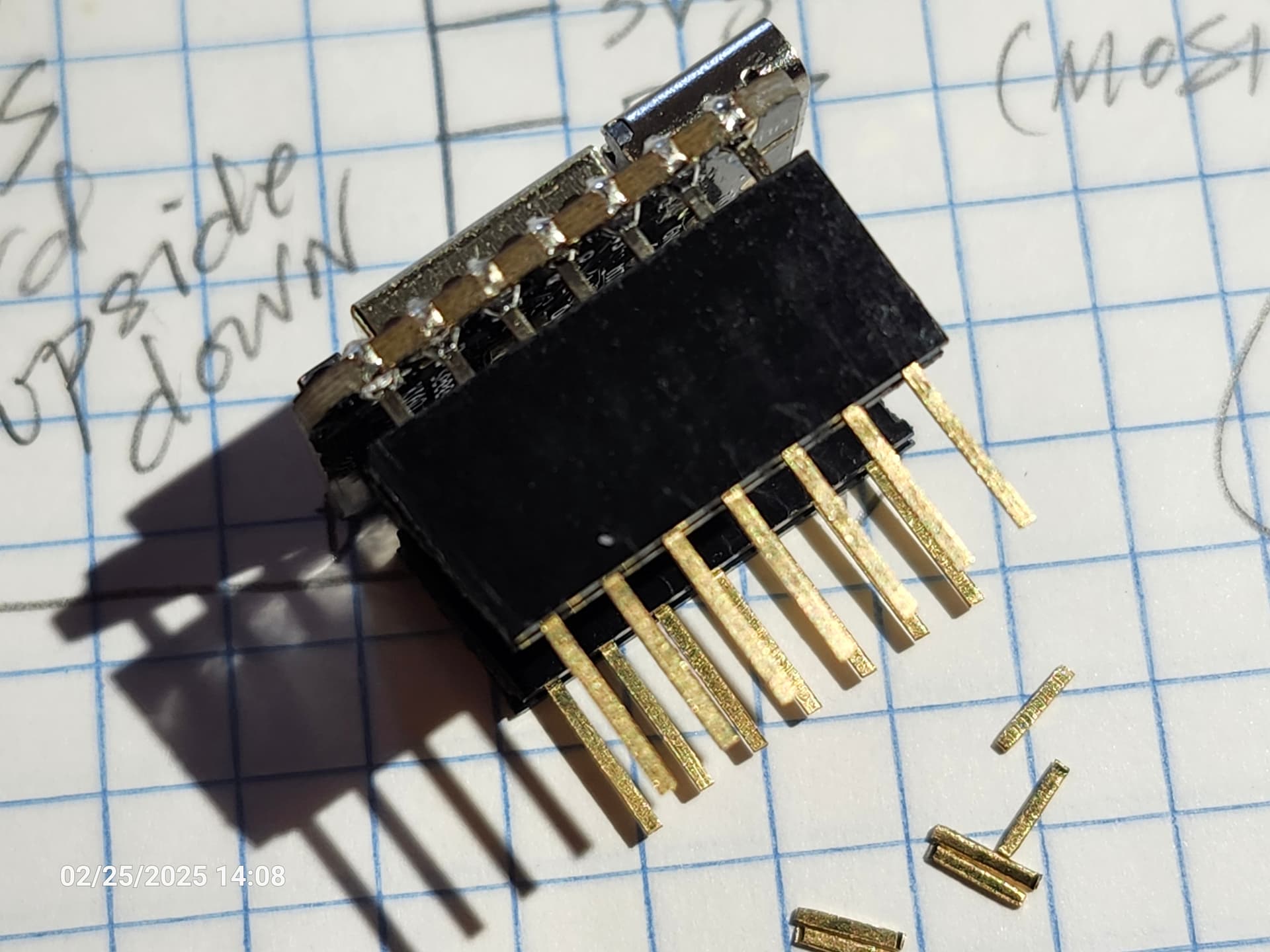
In order to install the GNSS module at the bottom of the XIAO Expansion board through pin to pin connection, it is necessary to resolder the female header of the XIAO Expansion board and replace it with a female header equipped with male pins.

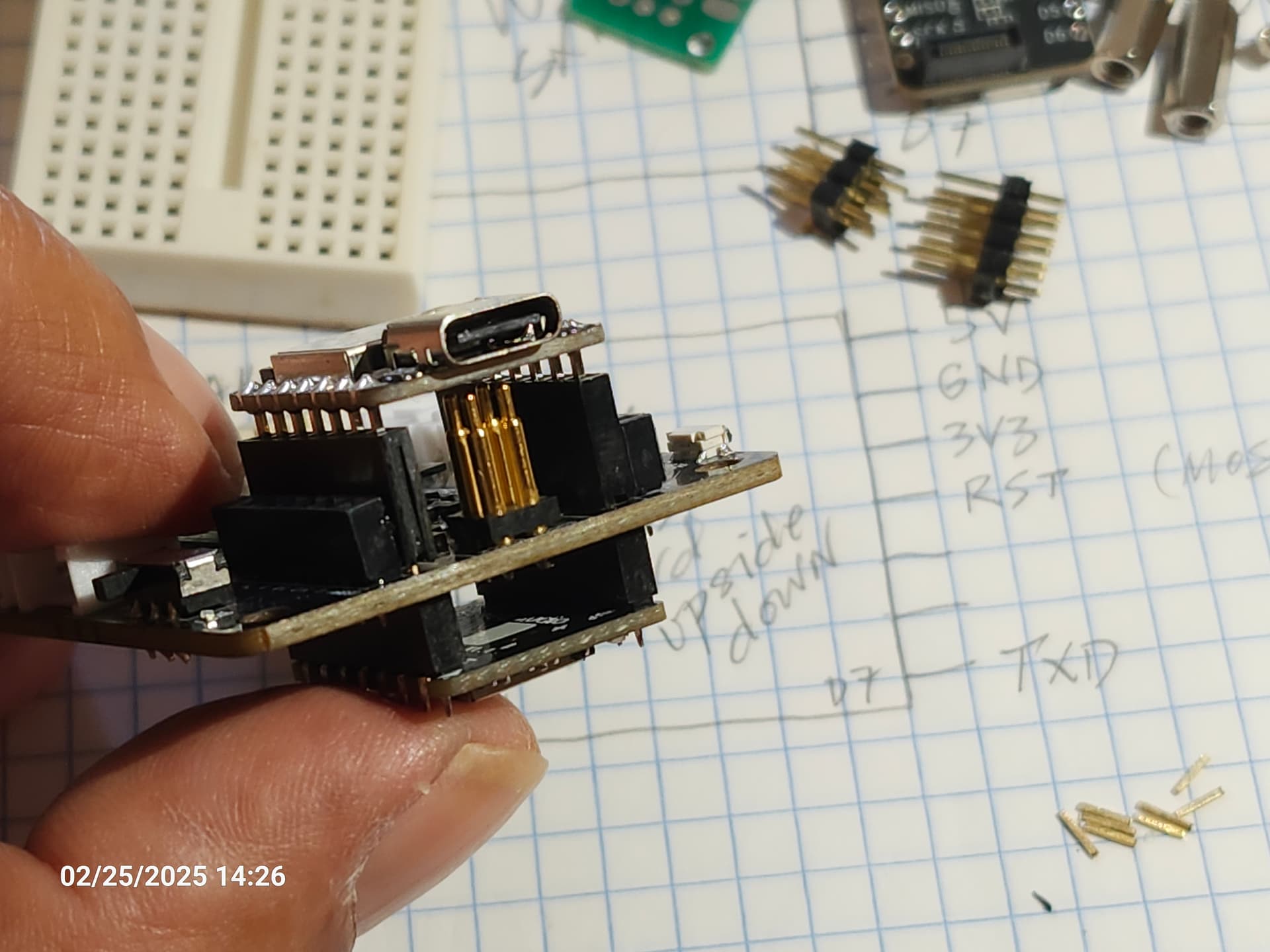
This seemed off from the start, as the pogos on the expansion board would be grounding on the shielding of L76 GNSS module. Right? In order to realise pin-to-pin connxn atop the expansion board the L76 module needs to be flipped upside down because of the board’s physical pin mapping.

So, seemingly placing the L76 GNSS board at the bottom, and stacking the ESP32S3 + Wio SX1262 above, is not going to work.

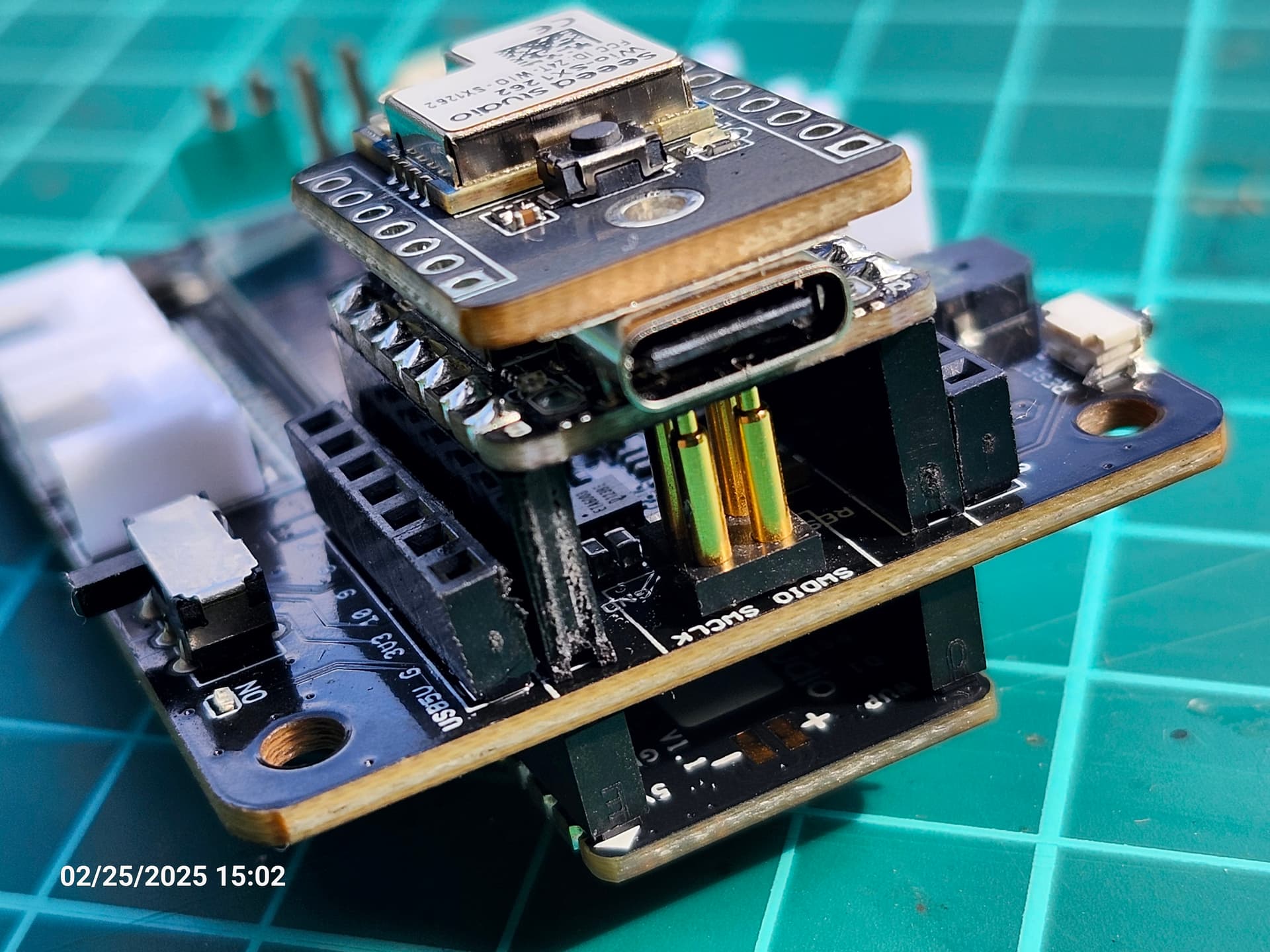
So, I thought, what about mounting the L76 atop the ESP32-LoRa boards as mounted atop the Xiao Expansion board? Well, how would I address the pin-to-pin connxns? Stacking headers all the way through? That’s like whacking down a handful of stacking headers to keep the profile low. And this begs the question of possible loss of B2B connxn between ESP32-S3 and its companion LoRa board. That question would be, “Will pin connections between ESP32-S3 and Wio-SX1262 retain same function whether I connect via pin headers or B2B connector?”

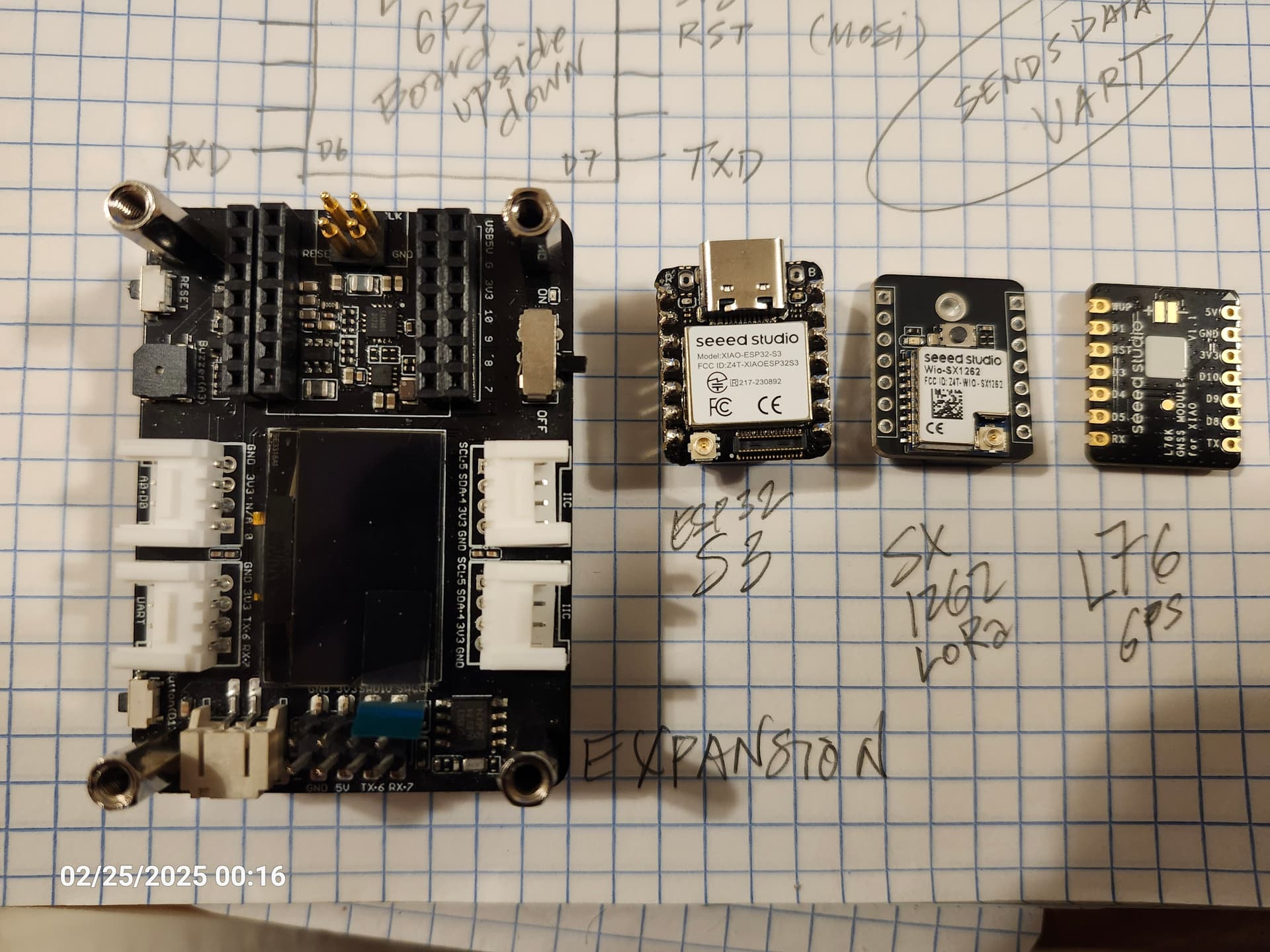
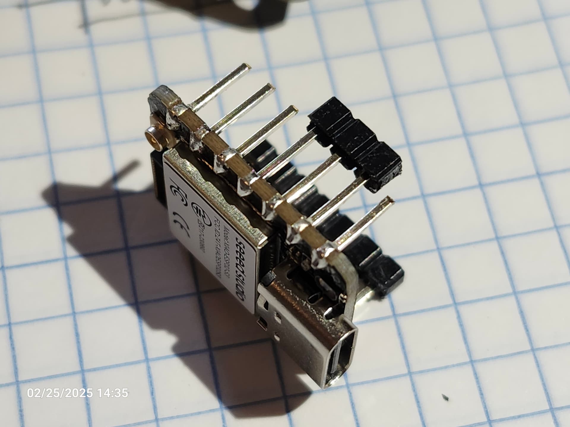
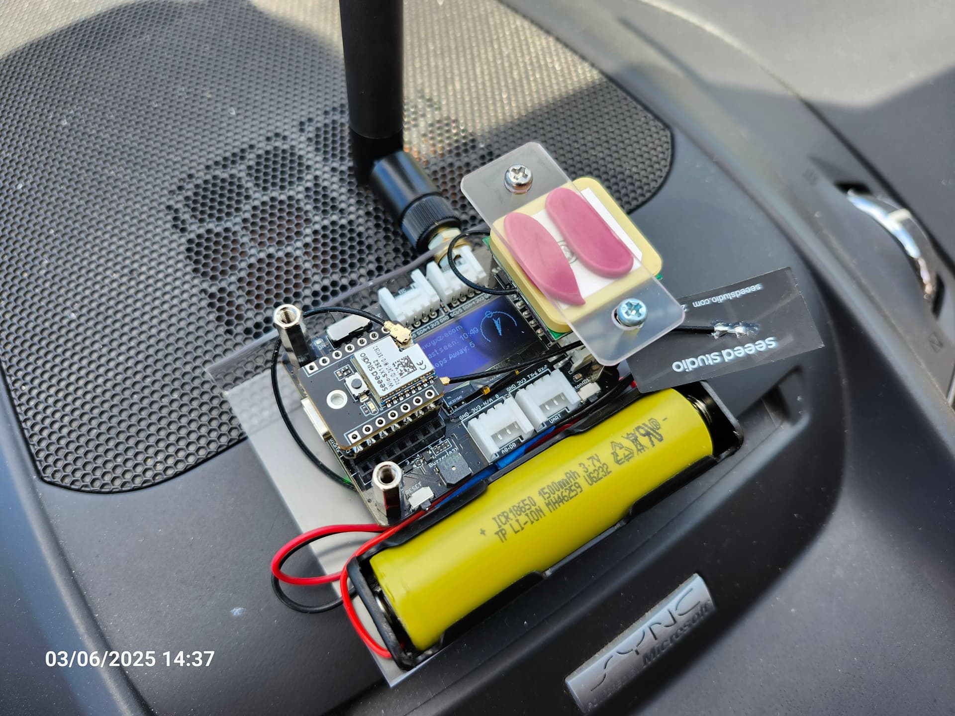
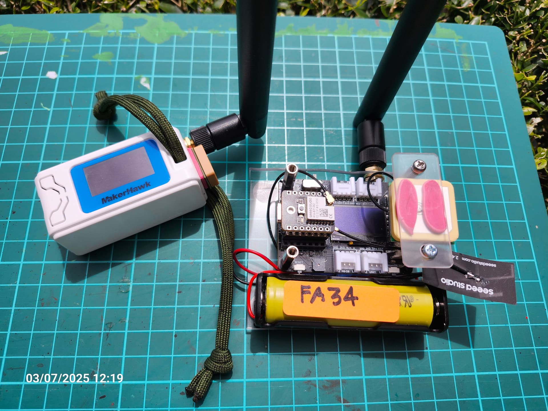
There is not a lot of documentation on this particular project. Any insights from those who have attempted this project would be very much appreciated. Included photo shows the boards I have at hand.

Thank you.

Hi there,

So the Lora board comes in several flavors, B2B (for direct attach to S3 sense) or SPI version or Uart version PIns 7 & 6 connected to Xiao(any of them)
I’m testing with a stack now with GPS , check out the other C3 multiple serial ports. I’m gonna go for S3 with 2 GPS , 1 Lora (B2B) Wifi, BLE and see if it works with expansion board.
Stay tuned.
Stack up works with S3 and GPS underneath(grn LED), I’ll put the lora card on when they arrive. :+1:


Serial output with WPS WiFi added and getting an IP address and syncing Sats…NICE!

Satellites: 5  Latitude: 26.041687  Longitude: -80.220941
WPS Successful, stopping WPS and connecting to: 
Disconnected from station, attempting reconnection
E (110943) wifi:sta is connecting, return error
Connected to :GlassSurf-2.4
Got IP: 192.168.1.172
Satellites: 5  Latitude: 26.041687  Longitude: -80.220941
Satellites: 5  Latitude: 26.041686  Longitude: -80.220940
Satellites: 5  Latitude: 26.041685  Longitude: -80.220940
Satellites: 5  Latitude: 26.041684  Longitude: -80.220939

HTH
GL :slight_smile: PJ :v:

runs on Battery too!

1 Like

@PJ_Glasso OK, so I am in the right place, and thank you for responding!

So, all I needed was a good night’s sleep.

Following is the steps I took to complete the Seeed 4-Layer Sandwich project. Please bear with me.


Like I said, a good night’s sleep…


So, there is a bit to overcome here to improve the fit and finish of the project. Using standard stacking headers the the pins dropping to the GPS board are a bit long. And, further eyeballin’ shows the need to remove the spacer below the S3 board for the pogo pins to hit right. A note on the pogo pins…yeah, plenty tension, blows the board upward over time. Am a bit reluctant at present to start bending male pins to increase friction in the female header. But, read on…


For this I used a piece of proto board as a spacer and the GPS’s included female headers as a gauge to trim the pins appropriately. Trimmed pins were deburred and rounded a bit, and cleaned.


Take a breath and admire the work so far.


Here I used the spacer as a gauge for trimming, with a flush cut at the spacer. Pins were deburred and rounded a bit.


Here we have the completed project, everything soldered in place, boards fitted.


With the pre-flashed Meshtastic on the Xiao ESP32-S3 + Wio-SX1262 kit, this board fired right up, detecting the L76 GNSS module and everything. Minor config via BT over phone and this is what is to be expected. Board started collecting nodes from around the area.

Project completion time was a leisurely 4 hours. So, yeah was a noobish question I posed above in regard this project. Begging your pardon with my presentation here.

edit: So, with all this, some of the tension in the pogo pins is relieved. A good ride in the truck will tell me if the connxns are solid in there.

All the best,
Bambuino

Hi there,

LOL, THAT is like a BOSS my Guy… LOOKS good. I’m sure with a 3D printed holder/enclosure it should be awesome. I say you got the mayo and the Tomato :grin: on that Xiao Sandwhich , we need more of those around here :+1:
I’ll be watching, Battery Size and What kind of Battery Life you get would be good to know also.
I’m sure there is a lot to discover so ONWARD :person_fencing:

GL :slight_smile: PJ :v:

Definitely some sleep code if the Sat data can handle it.

@PJ_Glasso Thanks man!
The biggest time suck on this project was de-soldering the header cleanly for dropping in the replacement stacking header. And, the pin length modifications, and the constantly refitting everything to check my work, and the … you folks get it.

I been using Nordic nRF24’s with AVR 328s and Tiny84s for years and was looking to try something different to achieve similar results. This was fun. Looking forward to playing with these Xiao boards, and hopefully provide some useful info to the folks here.

All the best,

1 Like