do you guys have a 3d model or even some “plan” dimensional drawings fo rthe odyssey?
I know it’s 110x110mm but i would like some dimensions for the screw holes, heights and header pins etc etc to make some cases and design brackets for hardware etc
do you guys have a 3d model or even some “plan” dimensional drawings fo rthe odyssey?
I know it’s 110x110mm but i would like some dimensions for the screw holes, heights and header pins etc etc to make some cases and design brackets for hardware etc
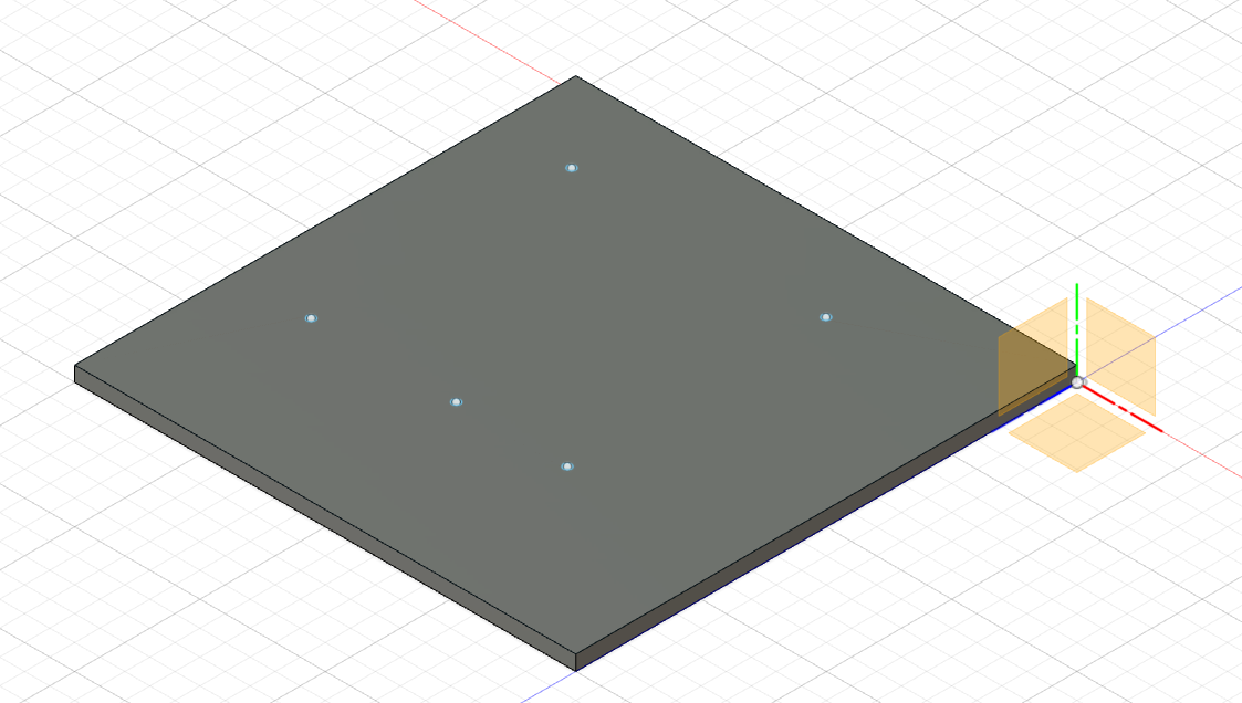
awesome i managed to get it into Fusion 360 and have a baseboard layout now ready so that I can start dealing with my case design.
Hi!
I see that the path for this .stp file is in the seed studios path, is it an official file that is linked to from their official wiki, and if so, what is that link, I can’t find it?
Hi, Yes this is the official. We have not updated this to the wiki yet, will update to the wiki very soon 
Also, when importing this into Fusion 360, the 5 mounting holes are spread across three different sizes, 0.056 in, 0.053 in, and 0.05 in, so I need the original mounting hole drawings.
Do you mind letting me what kind of format files that you will require, I’ll ask our Engineers to provide
Splendid - also, thank you for your quick reply!
Any image file will do that shows the centre of the holes, their diameter (or radius), and distances between the centres.
With that we can plug the data into any Cad/Cam package!
It is just the drawing that shows the dimensions that I want. It would, of course be helpful if the drawing also showed the location of the centre of the holes from the outside of the board.
Got it, will get back to you
@Xamtastic can’t you just measure it? I managed to get them from the model without an issue. Now i admit it took a little bit of work to remove all the extraneous stuff off of the 3d model, but i now have a flat plate that I can build from.
Also, the holes are M4/M5 I just drilled them out after 3d printing to make them fit the standoffs i was using
Oh, yes I can, I’ve got an adaptor plate exporting right now to the 3D printer. But for a supply line that considers interoperability (for example, allowing enough space for adjacent components), it is usual to for manufacturers to base all of their own components from a single set of drawings, otherwise tolerances can compound upon each others to create an error that is outside the original tolerance and before you know it, your product isn’t compatible with other 3rd party products.
I’m building an adapter plate for the Fibox 403021 Weatherproof enclosure here and if you click on the dimensional drawing link you’ll see how mounting holes are normally specified.
http://fibox.com/catalog/2389/product/9621/8120007_ENG3.html
Here’s a better drawing, in PDF format, it’s brilliant!
As an interim measure, the above file is fabulous, I’ve gone from that drawing to 3D print in a couple of hours, but it can’t be the final product spec because the 5 holes have 3 different sizes.
What particularly worries me is the centre hole on one side, it is extremely close to the headers and making a mistake with the tolerances here could result in the closest pin not being accessible by a 2.54 mm Dupont connector … and I wont know that until it is assembles.
I’m not expecting miracles, just asking a best-effort question.
they are M5 holes at least according to the board i have.
and my point was, once you have the layout then just use your model after that.
And there is no problems with the center hole on the one side. I have a ribbon cable plugged into it right now with a standoff in that position. and dupont connectors are not an issue at all either
How do you know whether there are any issues with the centre hole - as how do you know what diameter post I am attaching there, I don’t even know, because I don’t have the drawings, and what is certain. is that one of the wrong diameter will block a Dupont.
Anyway, thanks for helping, but as we’re having adapter plates manufactured in quantity, I can only base our measurements off the manufacturers drawings, this isn’t hobby project where the end user has access to drill to do their own drilling, my end users will just receive the item in the post and snap it in.
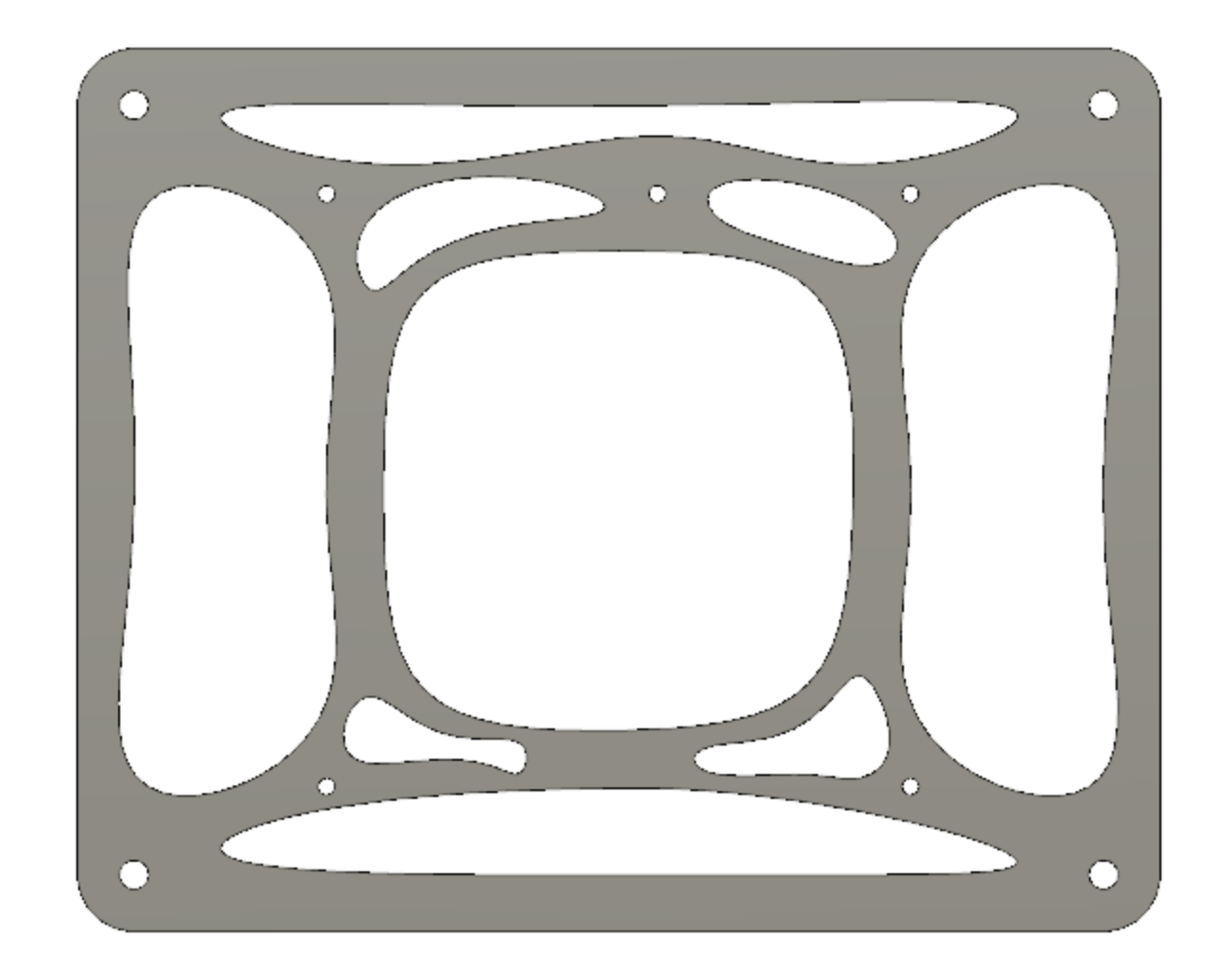
Here’s my temporary adapter plate, the spline holes are just to cut down on printing time, but I’ll have to start it from scratch when I get the drawings, to me it’s a loss of half a day not having them.
On an aside, the Odyssey is a brilliant product, we’re sticking it up 36 street light posts to monitor things.
my answer to that would be… do you not have the board in hand? do you not have a set of calipers? as a designer those i think would be the staple items you need.
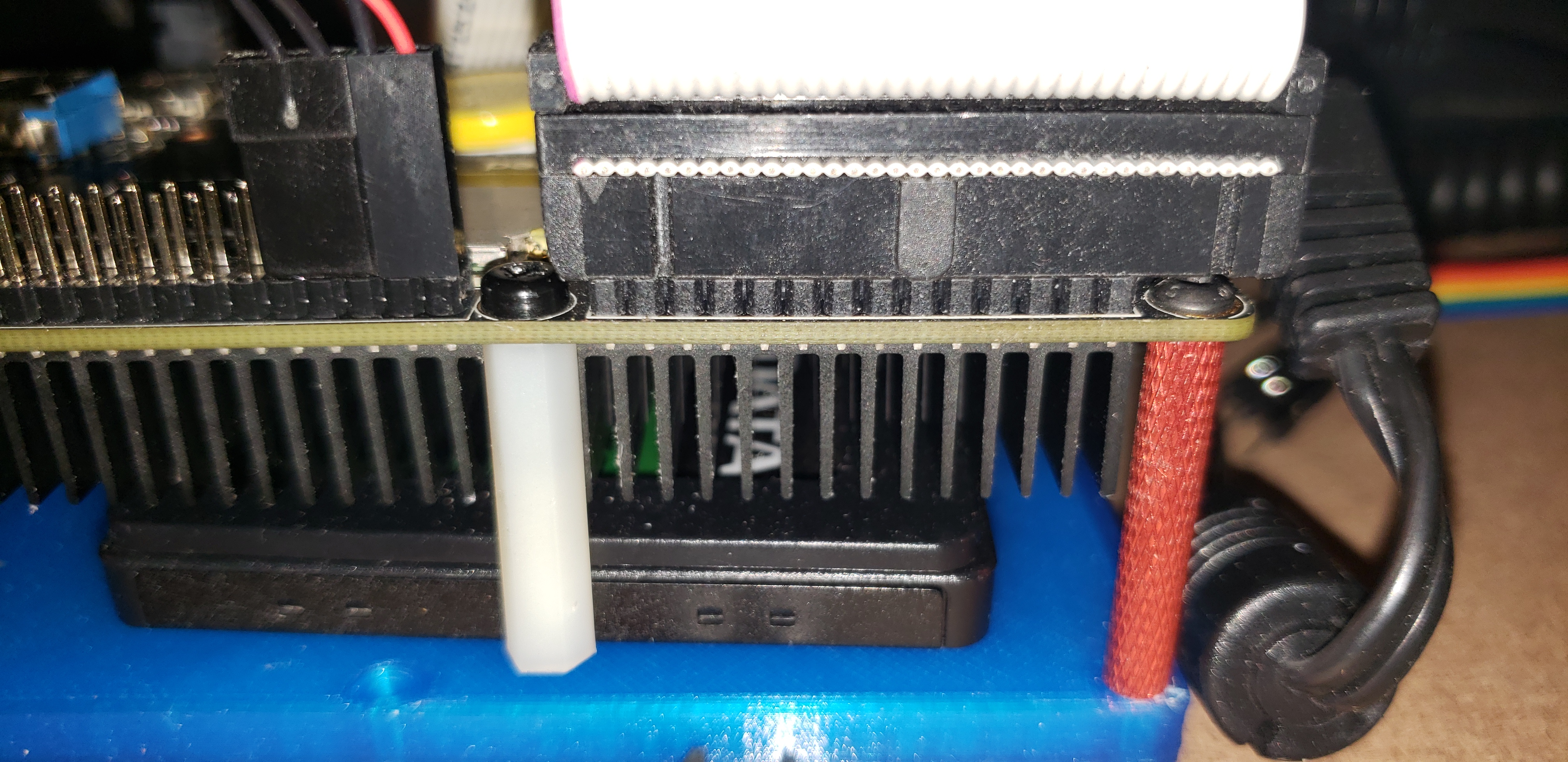
And as far as the center hole is concerned, I know for a fact it’s not blocking a dupont connector as that’s exactly what i’m using. as you can see in the attached image, here are the holes WITH standoffs as installed in my case.
i did goof on the base plate as this was the first “proof of concept” and not the finalised thing, but as you can see there is no clearance issue with either dupont OR IDC ribbon connectors. and as i said before i’m using M5 holes and M5 hardware
That adapter plate does look sweet though
This is how we do it in industry. We go to source, we verify, we put it all through a QA process. You can’t have QA without the original drawings. Of course I’ve got callipers, I can do this with my eyes closed, but we have higher standards.
Don’t get me wrong, I do take shortcuts for prototyping, but this is a production tack!
Oh, I like your risers - mine go up the other side - the Dupont side.
What’s your project?
Oh thanks! Check out Fibox for enclosures, the ARCA range is entirely weatherproof, you can put them at the bottom of a swimming pool, and they are big enough to put a small car battery in, great for outdoor R&D.
yea - having them go up the component side is going to be an issue for you, but you also have to remember there’s a heatsink on the other side and as I need access to the pins etc it makes sense to have the fan side up a little bit for airflow, but it just so happens that my 3.5" SSD fits under there too
My project is a ground control station for my UAV aircraft. allows me to see where they are on the map via telemetry and also decodes the ADSB data from commercial/GA aircraft.
This is eventually going to be used in conjunction with an antenna tracker for agricultural purposes, but my ulterior motive is that this is what I do for fun
I’ve been an electronics engineer for about 30 odd years give or take. I started on Z8/Z80 and 8031 micro-controllers
Wow, that’s astonishing, we’re essentially doing a similar thing, here’s my project, we’re presently building a grid of nodes, 6 by 6, 183 meters apart, as a demo: https://www.youtube.com/watch?v=0K6vrWz2AuQ
The feed goes into an azure event hub, the web address is on the video description, feel free to drop me an email, there might be an opportunity to collaborate!
I had an example of the new US Remote ID infrastructure working the same day their document was published (admittedly I got hold of a leaked copy the week before!).
We’re a UK operation, though.
On the Z80 side, I’ve been doing some 6502 assembly lately, just for fun … to distract me from Linux 64 NASM assembly, which I’ve had to write part of a Linux Kernel in assembly to get around a bug in the distro I’m using.
interesting, your ahem drone (i hate that word) laws over there are stricter and more shall we say… ridiculous than ours over here in the states (btw i’m english too, but live over here), that said. how do you plan for coping with drones that don’t carry them or are under 250 grams which wouldn’t need “remote id”