Does the WIO E5 Mini have a 3.3V power supply output? I want to use such output voltage from this device to power supply my temperature & humidity sensor. Especially when low power is enabled, this sensor will consume power only during this device’s activity period.
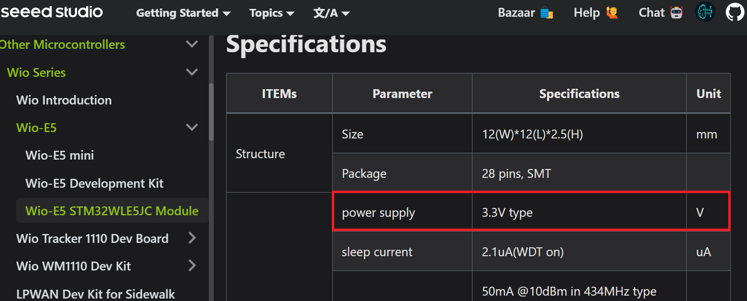
Well a simple search in the Seeedstudio would have given you the answer ![]()
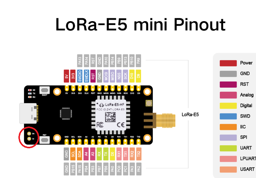
I know this page, but which pins are devoted to this output voltage? Are 3.3V and 5V output or input voltages?
What is this? I didn’t find any information about these pins.
Recheck page as all details are there ! Tip: you have the electronic diagram on that page…
OK, I will recheck.
But I have a question. Was answering my question according to this below, simple scout rule too hard?
- I know an answer; I share it with the community.
- I don’t know the answer; I don’t say anything.
It’s just quite annoying to answer always basic questions that are clearly documented and where you have all answers in documents published by the manufacturer ![]()
You have the full electronic schematic published by seeedstudio on their wiki where you can see easily that the 3.3V pin on the board is an output ![]()
Ok, thank you. Here’s one word from me. If I know something, then I try to share this knowledge. It shortens the time of searching for a solution for other people.
So I have a few questions if I can.
Which pin will be an input power supply from the battery? + and -? Or 5V + GND? What should be the level of voltage from the battery set when it will be + and -?
What will be the voltage from this 3.3V pin when the device enters the low power mode?
In my opinion, the device isn’t well and clearly documented when it comes to power supply, especially when anybody plans to power supply from a battery set.
As I said, it’s only my opinion.
How do you recognize that 3.3V is the output voltage?
I think you don’t read the documentation carefully.
So, how can you, reading the schematic, recognize that this pin is the output voltage?
According to the schematic,
Connect a nominal 3.7V battery to the + and - pads. There is no charging function on this board.
From the voltage supplied by the USB or battery, 3.3V (3V3) is generated by regulator U2:AP2112K for internal use and output from J1:pin2. It is not related to the low power mode of the device.