Hi, all!
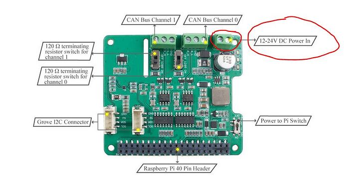
2 Channel CAN BUS FD Shield - Why do need “12-24V DC Power In”?
You don’t need to use the 12-24V input. See below it for the “Power to Pi Switch”
In the OFF position the USB or other 5V power source to the PI will power the CAN Hat.
In the ON Position the 12-24V input will power to Pi. 5V power to Pi via USB not needed. This is so the Pi can be powered in a vehicle without needed the 5V USB adapter.
I am currently prototyping a CAN Pi Dashboard and have the system doing basic functions with the USB attached and the “Power to Pi Switch” in the OFF position. Everything boots fine and I can write and read from the individual CAN bus modules using the can-utils after following the install guide on the product page.
Hope this helps!
The step down converter given within the schematics is capable to operate from 4.5 to 28V. Does anyone know why it needs to be 12V?
Would supplying 5V to the shield input work as well to supply the RPi, and would there be any drawback with it ?
If you don’t need it to power the RPI, you don’t need to care.
If I don’t needed to power the RPi I wouldn’t have asked:
I want to power the RPi thorugh the CAN FD hat.
This is mainly because in industrial scenarios it’s 12V.
 You are pretty careful, yes the buck IC working rang is 4.5-28. What we needed is 5V, the power in voltage must be higher than 7.6V then make sure the 5V output in heavy load is stable. We recomment is 12V, if you provide 8-12V, it’s ok.
