Hello,
I need to use more than one board (https://wiki.seeedstudio.com/Grove-12_Key_Capacitive_I2C_Touch_Sensor_V2-MPR121/) in my project. I noticed in the board’s description it is possible to use up to 3 boards at the same time. The point is to change I2C address of two boards to make possible using all of them together.
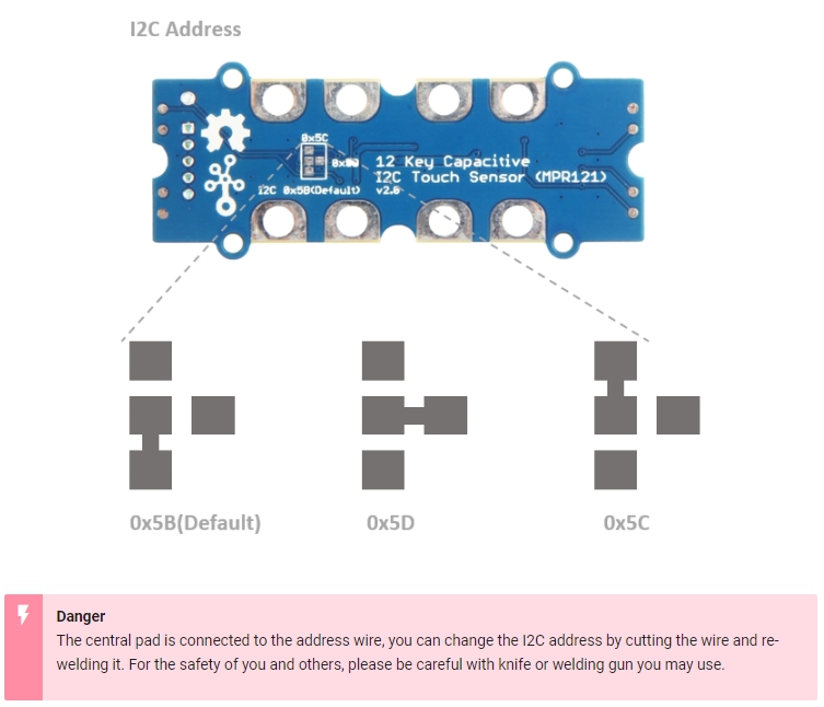
The description says “the I2C address is hardware configurable, from 0X5B to 0X5D” (0X5B is the default) and unfortunately I am not able to do it. I tried different ways as well as search in the Intenet for similar projects (using more than one board) with no result.
Can somebody do me a favor and explain step by step how to change this I2C address in hardware (or maybe in another way)? I would truly appreciate your help since I got stuck.
Best,
Michał
I already tried it before and it didn’t work out. I guess I did something wrong and I’ll try again. Thank you for the response
Okay, I managed to change the I2C address, now it is 0X5C instead of 0X5B (default) - I even checked by using I2C Scanner, so I’m sure it’s done properly.
The thing is the program I’m using doesn’t work with the board after changing I2C address. Not mention it doesn’t work with both of them at the same time as well. When I connect the previous board (0X5B) is still working.
Do you have any ideas what (or where) can be an issue?
It’s hard to guess without seeing the program.
Let’s say it’s extended ‘Leaf Piano’ program (‘Leaf Piano’ available here - https://github.com/SeeedDocument/Projects) but even the basic one does not work with different I2C address.
‘Leaf piano’ goes like that:
#include “MP3.h”
#include “Seeed_MPR121_driver.h”
MP3 mp3(2, 3);
Mpr121 mpr121;
uint8_t instrument = 1;
bool touchStatus[CHANNEL_NUM] = {0};
void setup() {
Serial.begin(9600);
while (!Serial);
if (mp3.init() && mpr121.begin() >= 0) {
Serial.println(“Initialize Success.”);
mp3.setVolume(0xff);
// mpr121.set_sensitivity(0x60);
} else {
Serial.println(“Initialize Failed.”);
}
Serial.println(
“Select a piece of instrument:\r\n”
“1 Piano\r\n”
“2 Drum\r\n”
);
}
void loop() {
uint16_t result = 0;
uint16_t filteredData[CHANNEL_NUM] = {0};
result = mpr121.check_status_register();
mpr121.get_filtered_reg_data((u16 *)&result, (u16 *)filteredData);
for (int i = 0; i < CHANNEL_NUM; i++) {
if (result & (1 << i) && !touchStatus[i]) {
touchStatus[i] = true;
mp3.play(instrument, i);
  // Serial.print("Note: ");
  // Serial.print(i);
  // Serial.println(" is pressed.");
} else {
  if (!(result & (1 << i)) && touchStatus[i]) {
    touchStatus[i] = false;
  }
}
}
if (Serial.available()) {
switch (Serial.read() - ‘0’) {
case 1:
instrument = 1;
Serial.println(“Piano is Selected.”);
break;
  case 2:
    instrument = 2;
    Serial.println("Drum is Selected.");
    break;

  default:
    break;
}
}
delay(50);
}
You write that it works with default address (0x5B).
When you try (0x5C), you have to change this line as well:
Mpr121 mpr121; -> Mpr121 mpr121 (0x5C);
So just try with this module to see if it works with this address.
I have ordered some pieces too, but it takes a while before they arrive.
Let me know how it goes.
It worked out, thank you for that.
Currently, I’m struggling with two boards working at the same time. If I find out how to change the code to make it possible I will let you know. In the meantime, if you have any ideas or suggestion about it, please feel free to share
Okay, I managed to figure out how to make two boards working simultaneously.
There is a need to:
- add another variable type MPR121,
- implement it inside the setup part of the code,
- add another variable type uint16_t,
- implement it inside the loop type ‘for’, responsible for checking the touch status.
Now the code goes like that:
#include “MP3.h”
#include “Seeed_MPR121_driver.h”
MP3 mp3(2, 3);
Mpr121 mpr121 (0x5B);
Mpr121 mpr122 (0x5C);
uint8_t instrument = 1;
bool touchStatus[CHANNEL_NUM] = {0};
void setup() {
Serial.begin(9600);
while (!Serial);
if (mp3.init() && mpr121.begin() >= 0 && mpr122.begin() >= 0) {
Serial.println(“Initialize Success.”);
mp3.setVolume(0xff);
// mpr121.set_sensitivity(0x60);
} else {
Serial.println(“Initialize Failed.”);
}
Serial.println(
“Select a piece of instrument:\r\n”
“1 Piano\r\n”
“2 Drum\r\n”
);
}
void loop() {
uint16_t result = 0;
uint16_t result2 = 0;
uint16_t filteredData[CHANNEL_NUM] = {0};
result = mpr121.check_status_register();
result2 = mpr122.check_status_register();
mpr121.get_filtered_reg_data((u16 *)&result, (u16 *)filteredData);
mpr122.get_filtered_reg_data((u16 *)&result2, (u16 *)filteredData);
for (int i = 0; i < CHANNEL_NUM ; i++) {
if ((result | result2) & (1 << i) && !touchStatus[i]) {
touchStatus[i] = true;
mp3.play(instrument, i);
// Serial.print(“Note: “);
// Serial.print(i);
// Serial.println(” is pressed.”);
} else {
if (!((result | result2) & (1 << i)) && touchStatus[i]) {
touchStatus[i] = false;
}
}
}
if (Serial.available()) {
switch (Serial.read() - ‘0’) {
case 1:
instrument = 1;
Serial.println(“Piano is Selected.”);
break;
case 2:
instrument = 2;
Serial.println(“Drum is Selected.”);
break;
default:
break;
}
}
delay(50);
}
I also noticed something weird to me in this line of code:
if (mp3.init() && mpr121.begin() >= 0 && mpr122.begin() >= 0) {
If you put ‘||’ instead of the second ‘&&’ and upload the program, it will work totally fine. But if you disconnect one of the board (by pulling the wire out of Arduino) and connect it again, it will no longer work even after resetting Arduino or uploading the program once more. I have no clue what can be the reason for this behaviour
I also had trouble understanding the instructions here for how to change the i2c address in hardware. I am used to bridging jump pads with solder but I was unclear on how to break the connection between the bottom and address pad.
I took an exacto-knife and stabbed around between the bottom and center address pad. I then checked using a multimeter to see if I had severed the connection between the pads.
Once I accomplished that, I formed a solder bridge between the center and top pad to use address 0x5c.
If anyone has clearer instructions besides “stab around the thin line between the bottom and center pad” I would love to hear it!