
Yes, I think it’s git that does some sort of conversion right when I upload things.
Would fix it, but my git knowledge is very limited 
First impressions. FFT seems to lose the ending frequency when going >= 5uS. I love the 2nd button press choosing the trigger levels. Very handy
Regards
Jerson
Yes, the FFT is a bit “crude”, but I just wanted to get a working version running. The thing with the ending frequency seems like a question of datatype or datatype conversion, but I didn’t really look into it.
I’ve also used the FFT with 1024 points instead of 256 and it runs without issues and is much more precise, but displaying that involves a bit more work, scaling the output to the display window (and I didn’t do that.)
The trigger level presets is all Marco’s work 
PS: oh, and I think I fixed the github binary files corruption thing…
[code]v1.13
- Corrections in the FFT calculations
(was making a mess, as usual)[/code]
Let me take this opportunity and give a big thanks to Pedro, Marco and others that have incrementally contributed to improving the s/w. I think this was the original intend of this product, and gracious individuals have taken upon themselves the task to deliver the s/w. BRAVO!
Yes, Marco and then Pedro did a great job, thank you very much. And the work of Pedro allows each of us to compile the firmware using a free compiler.
The integration of FFT is very nice but I don’t understand what it measures exactly. Look at the following example (230V mains with 10x probe):
[attachment=0]IMAG000.jpg[/attachment]
Two things irritate me:
[list]
Patrick
I would say the calculations are incorrect…
…or not.
I wouldn’t say an 8bit capture of a sine with about 30 samples per cycle like you show is a very good representation of a sine wave.
It’s a very poor one actually, and it would be strange to not get a lot of harmonics.
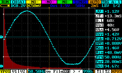
If you increase the time resolution (samples per cycle) you’ll start getting better results.
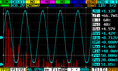
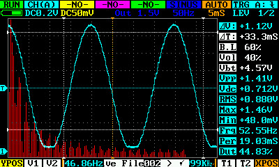
…but please remember - this is a 256 samples FFT.
It’s usefulness is limited.
Had some problems reverting back to the 1024 points FFT I had first implemented, and will probably not be trying to get it running any time soon.
If someone want’s to have a go at it… (all the FFT related code in the source is delimited with “// FFT” comments, and is actually very few lines of code)
[code]v1.14
- More (clueless) FFT tweakings
Replaced the Hanning Window
Applied dumb automatic scaling to the bars (based on max frequency)
Removed “bluring”[/code]
Download: https://github.com/pmos69/dso203_gcc/zipball/master
220 ac from wall it very very dirt source ))
because of many consumers like flyback power source, gas discharge lamp, etc
…right but compared to the awful “sine” of the quad, it is almost perfect 
Patrick
Yes, but sampling it with 8 bits will get it just as awful
[code]v1.15
- Small optimizations in some FFT operations
- Fixed FFT max frequency and scale max frequency display for time scales less than 10uS/Div[/code]
Hi Pedro
Wonder if you can look at this. I tried looking at the code, but can’t figure out where it is going wrong.
See this video that shows the GCC version in SCAN mode. Here you will see the waveform is printed in 3 distinct segments that repeat themselves.
http://youtu.be/2zUi5dcPvrQ
This is another video with the AP1_100 version in SCAN mode with buffer set to 360(smallest setting). This problem does not happen here. Sad we don’t have the sources for AP1_100
http://youtu.be/VU-VZ2kq62M
Please let me know if I there is a way I can help. Right now, I cannot figure out the whole code, so, not sure where to look. But, I am guessing SYNCHRO and PROCESS are the right places to look.
Regards
Jerson
sine wave of 220 with transformer
Hi chip,
…that means you can/will contribute to the project?
All the best,
Pedro
I’m sorry, but I have my own project.
Picture order was to compare. In 220 no loud noise.
No problem.
Do you have your source code available to the public?
no
220 ac spectrogram without second 100 Hz harmonic?
Very strange ))) just do not know what to suggest
How about your spectroscope dynamic range?
About the internal generator
It is far from perfect. At first - the signal from the DAC is not filtered. Second - the output buffer amplifier goes to a limiting on the signal levels close to GND and Vss, it is noticeable even visually, and produce harmonic components.