Lotus Cortex M0+ compile error working with FastLED

Dear All,


Has anyone successfully uploaded code with FastLED functionality form the Arduino IDE to the Lotos Cortex M0+? I see errors related to SPI pin assignment (see error log below).


I am using: Arduino 1.8.10, FastLED 3.3.2, Lotus Cortex M0+ v1.0 11/14/2018.


Found a page on FastLED that sort of explains the situation, copying the MKRZERO definitions does not work.

https://github.com/FastLED/FastLED/issues/414


Any ideas?


Thanks and regards,

–Aadjan


Error log:

----------------------------------------------------------------------------------------------------


Arduino: 1.8.10 (Mac OS X), Board: “Seeeduino Lotus - Cortex-M0+”


In file included from /Users/aadjan/Projects/Acting Machines/IDE Academy 191204/Solutions/button-blink/button-blink.ino:10:0:

/Users/aadjan/Documents/Arduino/libraries/FastLED/FastLED.h:585:2: warning: #warning “No pin/port mappings found, pin access will be slightly slower. See fastpin.h for info.” [-Wcpp]

#warning “No pin/port mappings found, pin access will be slightly slower. See fastpin.h for info.”

^

In file included from /Users/aadjan/Projects/Acting Machines/IDE Academy 191204/Solutions/button-blink/button-blink.ino:10:0:

/Users/aadjan/Documents/Arduino/libraries/FastLED/FastLED.h:14:21: note: #pragma message: FastLED version 3.003.002

pragma message “FastLED version 3.003.002”

                 ^<br/>

In file included from /Users/aadjan/Documents/Arduino/libraries/FastLED/FastLED.h:65:0,

from /Users/aadjan/Projects/Acting Machines/IDE Academy 191204/Solutions/button-blink/button-blink.ino:10:

/Users/aadjan/Documents/Arduino/libraries/FastLED/fastspi.h:130:23: note: #pragma message: No hardware SPI pins defined. All SPI access will default to bitbanged output

pragma message “No hardware SPI pins defined. All SPI access will default to bitbanged output”

                   ^<br/>

In file included from /Users/aadjan/Documents/Arduino/libraries/FastLED/FastLED.h:48:0,

from /Users/aadjan/Projects/Acting Machines/IDE Academy 191204/Solutions/button-blink/button-blink.ino:10:

/Users/aadjan/Documents/Arduino/libraries/FastLED/fastpin.h: In instantiation of ‘class FastPin<8u>’:

/Users/aadjan/Documents/Arduino/libraries/FastLED/fastspi_bitbang.h:22:49: required from ‘class AVRSoftwareSPIOutput<8u, 7u, 4ul>’

/Users/aadjan/Documents/Arduino/libraries/FastLED/fastspi.h:34:7: required from ‘class SPIOutput<8u, 7u, 4ul>’

/Users/aadjan/Documents/Arduino/libraries/FastLED/chipsets.h:157:6: required from ‘class LPD6803Controller<8u, 7u, (EOrder)10u, 4ul>’

/Users/aadjan/Documents/Arduino/libraries/FastLED/FastLED.h:253:77: required from ‘static CLEDController& CFastLED::addLeds(CRGB*, int, int) [with ESPIChipsets CHIPSET = (ESPIChipsets)5u; unsigned char DATA_PIN = 8u; unsigned char CLOCK_PIN = 7u; EOrder RGB_ORDER = (EOrder)10u]’

/Users/aadjan/Projects/Acting Machines/IDE Academy 191204/Solutions/button-blink/button-blink.ino:28:66: required from here

/Users/aadjan/Documents/Arduino/libraries/FastLED/fastpin.h:207:2: error: static assertion failed: Invalid pin specified

static_assert(validpin(), “Invalid pin specified”);

^

/Users/aadjan/Documents/Arduino/libraries/FastLED/fastpin.h: In instantiation of ‘class FastPin<7u>’:

/Users/aadjan/Documents/Arduino/libraries/FastLED/fastspi_bitbang.h:23:50: required from ‘class AVRSoftwareSPIOutput<8u, 7u, 4ul>’

/Users/aadjan/Documents/Arduino/libraries/FastLED/fastspi.h:34:7: required from ‘class SPIOutput<8u, 7u, 4ul>’

/Users/aadjan/Documents/Arduino/libraries/FastLED/chipsets.h:157:6: required from ‘class LPD6803Controller<8u, 7u, (EOrder)10u, 4ul>’

/Users/aadjan/Documents/Arduino/libraries/FastLED/FastLED.h:253:77: required from ‘static CLEDController& CFastLED::addLeds(CRGB*, int, int) [with ESPIChipsets CHIPSET = (ESPIChipsets)5u; unsigned char DATA_PIN = 8u; unsigned char CLOCK_PIN = 7u; EOrder RGB_ORDER = (EOrder)10u]’

/Users/aadjan/Projects/Acting Machines/IDE Academy 191204/Solutions/button-blink/button-blink.ino:28:66: required from here

/Users/aadjan/Documents/Arduino/libraries/FastLED/fastpin.h:207:2: error: static assertion failed: Invalid pin specified

/Users/aadjan/Documents/Arduino/libraries/FastLED/fastpin.h: In instantiation of ‘static void FastPin::fastset(FastPin::port_ptr_t, port_t) [with unsigned char PIN = 8u; FastPin::port_ptr_t = volatile long unsigned int*; RwReg = volatile long unsigned int; FastPin::port_t = volatile long unsigned int]’:

/Users/aadjan/Documents/Arduino/libraries/FastLED/fastspi_bitbang.h:175:45: required from ‘static void AVRSoftwareSPIOutput<DATA_PIN, CLOCK_PIN, SPI_SPEED>::writeBit(uint8_t, AVRSoftwareSPIOutput<DATA_PIN, CLOCK_PIN, SPI_SPEED>::clock_ptr_t, AVRSoftwareSPIOutput<DATA_PIN, CLOCK_PIN, SPI_SPEED>::data_ptr_t, AVRSoftwareSPIOutput<DATA_PIN, CLOCK_PIN, SPI_SPEED>::data_t, AVRSoftwareSPIOutput<DATA_PIN, CLOCK_PIN, SPI_SPEED>::data_t, AVRSoftwareSPIOutput<DATA_PIN, CLOCK_PIN, SPI_SPEED>::clock_t, AVRSoftwareSPIOutput<DATA_PIN, CLOCK_PIN, SPI_SPEED>::clock_t) [with unsigned char BIT = 0u; unsigned char DATA_PIN = 8u; unsigned char CLOCK_PIN = 7u; long unsigned int SPI_SPEED = 1ul; uint8_t = unsigned char; AVRSoftwareSPIOutput<DATA_PIN, CLOCK_PIN, SPI_SPEED>::clock_ptr_t = volatile long unsigned int*; AVRSoftwareSPIOutput<DATA_PIN, CLOCK_PIN, SPI_SPEED>::data_ptr_t = volatile long unsigned int*; AVRSoftwareSPIOutput<DATA_PIN, CLOCK_PIN, SPI_SPEED>::data_t = volatile long unsigned int; AVRSoftwareSPIOutput<DATA_PIN, CLOCK_PIN, SPI_SPEED>::clock_t = volatile long unsigned int]’

/Users/aadjan/Documents/Arduino/libraries/FastLED/fastspi_bitbang.h:345:14: required from ‘void AVRSoftwareSPIOutput<DATA_PIN, CLOCK_PIN, SPI_SPEED>::writePixels(PixelController<RGB_ORDER>) [with unsigned char FLAGS = 0u; D = DATA_NOP; EOrder RGB_ORDER = (EOrder)10u; unsigned char DATA_PIN = 8u; unsigned char CLOCK_PIN = 7u; long unsigned int SPI_SPEED = 1ul]’

/Users/aadjan/Documents/Arduino/libraries/FastLED/chipsets.h:138:3: required from ‘void WS2801Controller<DATA_PIN, CLOCK_PIN, RGB_ORDER, SPI_SPEED>::showPixels(PixelController<RGB_ORDER>&) [with unsigned char DATA_PIN = 8u; unsigned char CLOCK_PIN = 7u; EOrder RGB_ORDER = (EOrder)10u; long unsigned int SPI_SPEED = 1ul]’

/Users/aadjan/Projects/Acting Machines/IDE Academy 191204/Solutions/button-blink/button-blink.ino:44:1: required from here

/Users/aadjan/Documents/Arduino/libraries/FastLED/fastpin.h:229:21: warning: unused parameter ‘port’ [-Wunused-parameter]

Multiple libraries were found for “FastLED.h”

Used: /Users/aadjan/Documents/Arduino/libraries/FastLED

inline static void fastset(register port_ptr_t port, register port_t val) attribute ((always_inline)) { }

^

/Users/aadjan/Documents/Arduino/libraries/FastLED/fastpin.h:229:21: warning: unused parameter ‘val’ [-Wunused-parameter]

/Users/aadjan/Documents/Arduino/libraries/FastLED/fastpin.h: In instantiation of ‘static void FastPin::fastset(FastPin::port_ptr_t, port_t) [with unsigned char PIN = 7u; FastPin::port_ptr_t = volatile long unsigned int*; RwReg = volatile long unsigned int; FastPin::port_t = volatile long unsigned int]’:

/Users/aadjan/Documents/Arduino/libraries/FastLED/fastspi_bitbang.h:176:49: required from ‘static void AVRSoftwareSPIOutput<DATA_PIN, CLOCK_PIN, SPI_SPEED>::writeBit(uint8_t, AVRSoftwareSPIOutput<DATA_PIN, CLOCK_PIN, SPI_SPEED>::clock_ptr_t, AVRSoftwareSPIOutput<DATA_PIN, CLOCK_PIN, SPI_SPEED>::data_ptr_t, AVRSoftwareSPIOutput<DATA_PIN, CLOCK_PIN, SPI_SPEED>::data_t, AVRSoftwareSPIOutput<DATA_PIN, CLOCK_PIN, SPI_SPEED>::data_t, AVRSoftwareSPIOutput<DATA_PIN, CLOCK_PIN, SPI_SPEED>::clock_t, AVRSoftwareSPIOutput<DATA_PIN, CLOCK_PIN, SPI_SPEED>::clock_t) [with unsigned char BIT = 0u; unsigned char DATA_PIN = 8u; unsigned char CLOCK_PIN = 7u; long unsigned int SPI_SPEED = 1ul; uint8_t = unsigned char; AVRSoftwareSPIOutput<DATA_PIN, CLOCK_PIN, SPI_SPEED>::clock_ptr_t = volatile long unsigned int*; AVRSoftwareSPIOutput<DATA_PIN, CLOCK_PIN, SPI_SPEED>::data_ptr_t = volatile long unsigned int*; AVRSoftwareSPIOutput<DATA_PIN, CLOCK_PIN, SPI_SPEED>::data_t = volatile long unsigned int; AVRSoftwareSPIOutput<DATA_PIN, CLOCK_PIN, SPI_SPEED>::clock_t = volatile long unsigned int]’

/Users/aadjan/Documents/Arduino/libraries/FastLED/fastspi_bitbang.h:345:14: required from ‘void AVRSoftwareSPIOutput<DATA_PIN, CLOCK_PIN, SPI_SPEED>::writePixels(PixelController<RGB_ORDER>) [with unsigned char FLAGS = 0u; D = DATA_NOP; EOrder RGB_ORDER = (EOrder)10u; unsigned char DATA_PIN = 8u; unsigned char CLOCK_PIN = 7u; long unsigned int SPI_SPEED = 1ul]’

/Users/aadjan/Documents/Arduino/libraries/FastLED/chipsets.h:138:3: required from ‘void WS2801Controller<DATA_PIN, CLOCK_PIN, RGB_ORDER, SPI_SPEED>::showPixels(PixelController<RGB_ORDER>&) [with unsigned char DATA_PIN = 8u; unsigned char CLOCK_PIN = 7u; EOrder RGB_ORDER = (EOrder)10u; long unsigned int SPI_SPEED = 1ul]’

/Users/aadjan/Projects/Acting Machines/IDE Academy 191204/Solutions/button-blink/button-blink.ino:44:1: required from here

/Users/aadjan/Documents/Arduino/libraries/FastLED/fastpin.h:229:21: warning: unused parameter ‘port’ [-Wunused-parameter]

/Users/aadjan/Documents/Arduino/libraries/FastLED/fastpin.h:229:21: warning: unused parameter ‘val’ [-Wunused-parameter]

exit status 1

Error compiling for board Seeeduino Lotus - Cortex-M0+.


This report would have more information with

“Show verbose output during compilation”

option enabled in File -> Preferences.

I did some more searching and found that apparently the Lotus Cortex M0+ does not expose the SPI pins(!). SAMD21 pins PA12 and PA13 (SPI pins MOSI and MISO) are not routed on the board (I cannot find them in figure 2 on the wiki page of the board).


The lotus Cortex M0+ will never be able to run SPI based Arduino libraries? I found one example of where this breaks our routine using FastLED in our education program, still investigating what other libraries we commonly use will break on this lotus board.


If Weifeng Zeng is reading this I would love to know the rational for not including SPI. One more feedback for the board is that it is strange to promote SerialUSB as the main serial port for doing debugging in the Serial Monitor of the Arduin IDE. This means everybody using the board will first make the mistake by not seeing the serial output in the usual place and on top of that there are two version of Serial printing if you move back and forth from the Lotus v1.1 to the Lotus Cortex M0+. (The folks at Arduino did it right on the Arduino Nano 33 IOT.)


Still digging,

–Aadjan

I’m also struggling witht the Lotus Cortex M0+.

It looks great with the LiPo chargin and the grove breakouts but some of the base libraries are missing and the documentation is a bit lacking.

You have to dig into the variant.cpp file to see the pin assignment but it seems to contradict the schematic in some areas…


Don’t know if it answers your question, but the SPI port is broken out on the ICSP port, although you’ll find different pinout information depending on where you look:


The lotus\variant.cpp file says this:

[attachment=1]variant.cpp.png[/attachment]


But the schematics says this:

[attachment=0]breakout.png[/attachment]

[size=120]Notes:[/size]
[list=]

  • [*]Variant file found in: [code] %LOCALAPPDATA%\Arduino15\packages\Seeeduino\hardware\Seeeduino_SAMD_zero\1.0.0\variants\lotus [/code]
  • [*]Schematics found in the Wiki: [url]http://wiki.seeedstudio.com/Seeeduino_Lotus_Cortex-M0-/#resources[/url]
  • [/list] ![breakout.png|399x445](upload://u4T5qY9qfPw4UiSTKKxizk2JKxH.png) ![variant.cpp.png|684x124](upload://oHkhwmFOHun5oPh5GYPDOOxJM41.png)

    Hi Renaud.Bompuis,


    Thanks for finding the MOSI and MISO port on the board! I am happy that they are actually there (have not tested this yet).


    Your find helped me to dig deeper into the problem. Which as it turns out is not related to the physical MOSI and MISO ports after all. It is just that de board definition is conflicting with the FastLED library. The board definition is currently configured to fall into the software SPI segments of the code and then compilation fails on that (my next guess of what goes wrong).


    In addition I have the issue that I want the board to identify Serial as pointing the the default channel for the Serial Monitor window. As the board is currently defined every bit of example code you pull from the internets you have to redirect serial output to SerialUSB, this is a serious pitfall for our students.


    As you were the only one responding in a couple of weeks, I will use my Seeedstudio sales contact to see if I can find answers through that channel as well. Will report back here if I do.


    Kind regards,

    –Aadjan

    Let me start by saying that this is my first seeeduino board. However I have been very active with these types of boards going back way before the PICs and Motorola 68xx series


    I just received my order for a Seeeduino Lotus Cortex-M0+ board. My first observation is that the Seeeduino Wiki installation article has a lot of errors and inconsistencies in it.


    1. when you connect the board to your PC, the Device Manager identifies the board as Seeeduino-lotus under Other Devices. When you try to update the driver of Seeeduino_lotus, you have only 2 ways to do the upgrade, through Windows Update and Finding a file on your PC


    2. Windows Update path does not work because that file does not just exist anywhere out there


    3. Find a file on your PC is leads you nowhere because that file just does not exist on your PC


      So I decided to take a look inside the boards json file

      <LINK_TEXT text=“https://raw.githubusercontent.com/Seeed … index.json”>https://raw.githubusercontent.com/Seeed-Studio/Seeed_Platform/master/package_seeeduino_boards_index.json</LINK_TEXT>


      I noticed that all references to Lotus are listed under ----- guess what

      “name” : “Seeeduino AVR”,

      “architecture” : “avr”,

      “version” : “1.2.1”,

      below seeeduino avr architecture, if you examine the boards listing you find Seeeduino Lotus listed!!!


      The Seeeduino Lotus Cortex-M0+ is a SAMD board! and nowhere in the listing for SAMD architecture is a Seeeduino Lotus board listed!!!

      I’d suggest that you take the time to look into that json file


      Could any Seeedstudio engineer confirm how you expect to have a proper com port listed for an architecture for which no driver upgrade path exists!


      Where is the driver for Seeeduino_lotus file located in order to allow the update to be done???


      This is my first Seeeduino board and although very disappointed, frustration has not set in yet!

    While support for Windows 7 from Microsoft has ended, there are still quite a number of people using Windows 7.


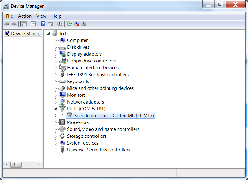
    We had a drivers issue when trying to use a Lotus Cortex Mo+ board. That issue has been resolved.


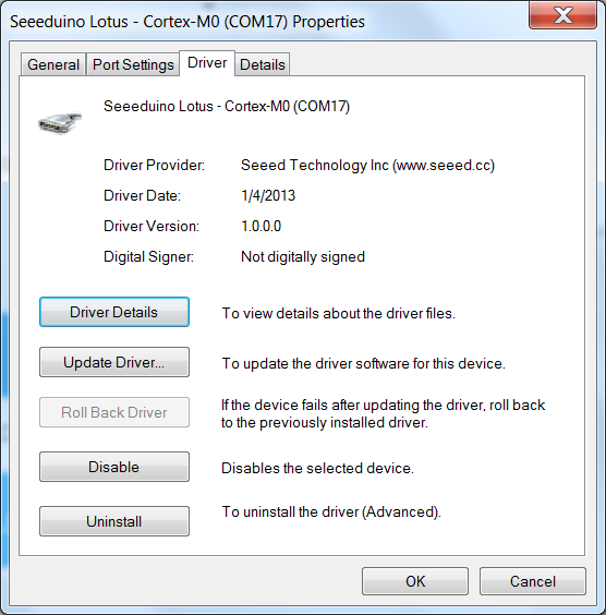
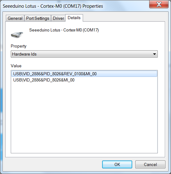
    SeeedStudio did update the drivers for the Cortex M0_ board but did not update the installer. The PID is 8026 and Windows 7 expects a driver with PID of 8026 before it recognises that driver as being compatible.


    Since we cannot non graphic files here you may contact SeeedStudio support to send you the URL or you may contact me directly if you want. Please note the file is a zipped file


    Happy New Year of the rat to all


    Cheers


    Gipsyblues
    WIN 7 SCREEN SHOWING DEVICE DRIVER PAGE.png
    WIN 7 SCREEN SHOWING CORRECT  DRIVER INSTALLED AND CORRECT COM PORT.png
    WIN 7 SCREEN SHOWING PID FOR DRIVER REQUIED.png