XIAO with DS18B20 sensor

@PJ_Glasso
Hi thanks!
Have you did some testing about SAADC with double buffering through PPI settings and related timer attached to perform DMA buffer update after the sampling completed?

I’m looking to implement such way to perform some real time signal anaysis with the XIAO nRF52840 sense board.

At now the only timer usable looks to me Timer3 or Timer4 because:

  • Timer0 : used by sofdevice s140 (I need to use also BLE)
  • Timer1 : from my understanding it is used by Mbed OS
  • Timer2 : if I’m right it is used by the ArduinoBLE (should it based on ble cordio)

In your perspective I’m right about above considerations?

BR
Fire

Hi there,
Yes, Only timer 3 or 4 can be used as the T1 is used internal.
There is another Library to try also.
To do DMA though it’s not needed just the pointer is. It does work.
search the threads there’s one that addresses it.
HTH
GL :slight_smile: PJ
:v:

Thanks for your confirmation.
Well trying with a code that is able to work properly inside Segger Embedded Studio (SES) with SDK 17.0.2 give me following errors:

  • undefined reference to ‘nrfx_timer_init’
  • undefined reference to ‘nrfx_timer_extended_compare’
  • undefined reference to ‘nrfx_timer_enable’

after searching a little I’ve reached this post:

https://github.com/arduino/ArduinoCore-nRF528x-mbedos/issues/58

so at this point I’m pretty sure the problem lies in the precompiled library libmbed.a which was not compiled with the timer enable flag set to 1 inside the sdk_config.h file. So the solution that was presented was to produce a new libmed.a library, but I’ve never done this before and from what I can read it seems “simple”, but at this time I haven’t found a usable post that lists the steps that should be done to compile this library in Windows for XIAO nRF52840 sense board and that is also able to work properly inside the Arduino IDE…

Thanks and BR
Fire

Hi there,
Yes, I would look to another third party Timer LIB that would work.
HTH
GL :slight_smile: PJ

@PJ_Glasso
Hi found a solution on this thread:

using the code provided in this example I was able to get all stuff working together but I’ve a suspect that this is just continuos sampling and not double buffering.

BR
Fire

1 Like

Nice going… Yes probably is continuous sampling , but if its getting data, Right ON!
:slight_smile:

@PJ_Glasso
Now I’m measuring timing with scope in order to check if the processing time is less than the sampling interval in order to be sure that I’m not lost some data… but it would be the best approach have the double buffering operative, I think that is the best approach to use…
I can see that the sampling interval is about 200us (fs=5kHz), the copy data also have a small execution time but this time plus the one needed to enter into the FSM and execute the copy data lost data from the input so double buffering is a must if we have to perform a real time data processing… do you have some idea how to set up double buffering here?

BR
Fire

1 Like

@PJ_Glasso
Ok double buffering implemented and able to work.
Actually I can sample at 500Hz three analog inputs and perform also a 4 order digital filtering on each channel and send data through serial link at 115200 bps, and I’m at the limit of timing also with the double buffer (mainly due to the time required to send the data out through the Serial.println() method).

In order to increment the performance by reducing the time required to the signals elaboration I’m looking how is possible to change the compiler settings for the g++ used in order to set the the optimization switch to -O2 (Level 2 - speed optimization) because actually I think that this switch is set to the -Os (space optimization). Do you have some idea?

All the three input signals are tied together to see if all the analog inputs have same responce and get the 50Hz signal from a Current Transformer with the reported schematic.

Into the following image the blue plot is the input, the red and green are t
he digital filtered output waveforms.

Thanks
BR

2 Likes

Dear all,
to complete this example I’ll put here the full sketch listing and some explanations.

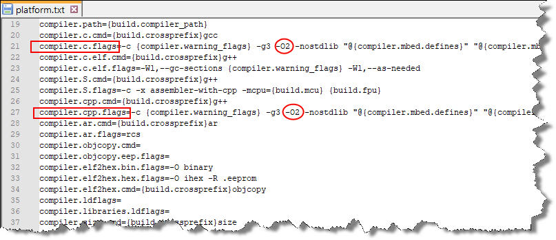
To get all working you have to perform a change into the optimization flag for the gcc compiler, to do that go at the following boards folder (I’m using the 2.7.2 Mbed OS version):

C:\Users…\AppData\Local\Arduino15\packages\Seeeduino\hardware\mbed\2.7.2

with a text editor open the platform.txt file and perform a search for compiler.c.flags then put after the -g3 option the -O2 optimization switch.
Perform another search for compiler.cpp.flags and again put just after the -g3 option the -O2 optimization switch.

then just run the sketch and all should be able to work properly.

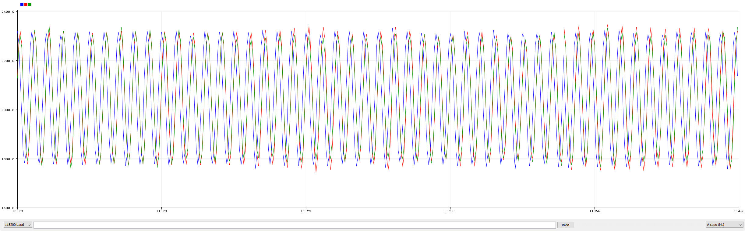
The reading loop about the SAADC is fired every 2ms (the sampling frequency was set to 500Hz) and a buffer of 1000 samples (DATA_BUFFER_SIZE) have to be filled before data will be sent through the serial port, so to perform any data elaboration we have an interval of 2".

The code I’ve written implement a double buffering software approach so, briefly, suppose that the SAADC is filling the three buffers dataBuffer1[0][], dataBuffer2[0][] and dataBuffer3[0][] under the ISR code SAADC_IRQHandler_v (I’ve planned three analog source to be sampled), in this time the other three buffers dataBuffer1[1][], dataBuffer2[1][] and dataBuffer3[1][] are processed into the main loop code.

When the dataBuffer1[0][], dataBuffer2[0][] and dataBuffer3[0][] are fully filled the global buffers index bfrIdx switch from 0 to 1 so within the next 2" time window the buffers that will be filled from the SAADC will be the dataBuffer1[1][], dataBuffer2[1][] and dataBuffer3[1][] and then into the main loop we have to process the previosuly filled dataBuffer1[0][], dataBuffer2[0][] and dataBuffer3[0][], and so on…

Obviously to avoid any loss of data is important that these three buffers are fully processed into the main in a time that must be less than 2".

Using such approach we just have care to be sure that the main processing loop will finish before all the data is filled inside the other three buffers group currently managed under the SAADC ISR handler.

If you look directly at the code this approach will appear more simple that the description above.

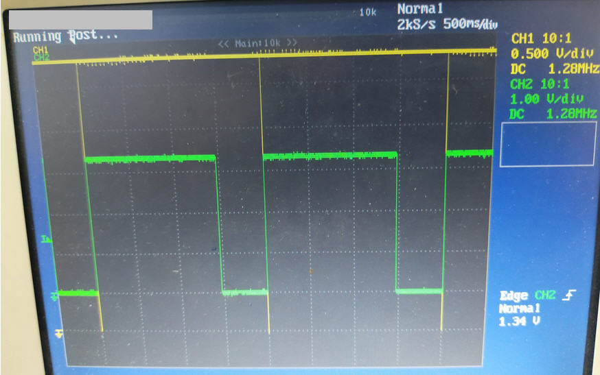
Into the code you can see some NRF_P1->… statements, these one are used to trigger some output pin used to debug the code and verify that the timing described above are respected (pin D6 and D7), into the screenshoot below in yellow there is the ISR timing (every 2" the buffers are filled) and the green wave is about the data processing function, filtering and data serial sending by means of the elabData() function.

Digital filtering is made through the filtering1(), filtering2() and filtering3() functions, actually these perform same filtering, here is the place where you can change the filtering strategy. Remember to design the filter according the sampling frequency! Actually the filter is a IIR implemented with first direct form. IIR filters are shorter than FIR filters if compared to same filtering performances, but can going to be unstable so carefully check the behavior and the implementation used.
In this example I’ve used this online tool:

https://www.meme.net.au/butterworth.html

of course you can also design your one filter and check about it performance through the Scilab or Matlab tools, there are many tutorial (theoretical and practical) around the web about signal processing and digital filtering and this field is very amazing.

Hope such things can be useful for someone, of course let me know if you have improvements and other useful things about!!

Best regards.
Fire aka Powemos

xiao_nrf52840_esempio8.zip (6,7 KB)

1 Like

Hi there,
WoW, Yes you brought the receipts :slight_smile:
So it defaults to space because of the majority of the Aduinos were small memory devices, I can see this being used for and HIGHER speed data acquisitions to try the SPeed switch. Kinda like oversampling during the time allotted. very cool find, I had no idea you could switch. Great Info.
GL :slight_smile: PJ
:v: