XIAO with DS18B20 sensor

For starters, disconnect the DS18B20, and anything else you happen to have connected to your XIAO BLE board and see what happens.

Here’s what happened when I ran your code:
The Blue LED on my XIAO BLE Sense blinked at a rate of four per second.

Here’s why:

Arduino pin 12 is actually CPU GPIO pin P0.06, which is connected to the cathode of the Blue part of the RGB LED.

The code in the loop sends a 480 microsecond “DS18B20 Reset” low pulse every 250 milliseconds. There’s nothing to respond (by pulling the DQ line low after the “Reset” pulse returns high), so ds.search() fails, and the code prints “No more addresses.” each time through the loop.

Now, if you want to see some action on The XIAO BLE Sense Pin 2, change your OneWire object instantiation to something like this:

// Note that a 4.7K Pullup resistor from DQ to 3.3V is recommended
OneWire  ds(2);  // DS18B20 DQ Line to XIAO Pin 2

Now, I don’t have a Grove DS18B20 sensor, but its Wiki page indicates that you need the external 4.7K Ohm pullup to Vdd. I guess it’s just a barefoot DS18B20 device with some waterproofing and a cable.

Anyhow…
With a pullup resistor on Pin 2 and no DS18B20, I see the Reset pulse.

Regards,

Dave

Footnote: If you can continue operating after going into boot mode, there’s a good chance that your XIAO is OK. I didn’t have your reboot problem with this sketch, but I have seen some strange behavior with (Other People’s) sketches that use “unusual” GPIO pins in unintended ways.

@davekw7x , yes after boot mode all comes back to the operation. I tried to change to pin 2 - same result.
with regards to 4,7k resistor - in the it says it is already inside of the item.
i will continue to dig then.

Arduino pin 12 is actually CPU GPIO pin P0.06, which is connected to the cathode of the Blue part of the RGB LED.
is there any comparison table Arduino Pin X = Pin Xiao=Pin Xiao expansion board?

@leroyle - yes i am using XIAO expansion board, will try to run the code on breadboard today, let’s see the result.
thank you all, will keep trying to find the solution

I recently posted tables that are in variants.cpp for board package 1.0.0 and 2.7.2 here:
Totally new in this and need a basic question answered… (How to map device pin with pin numbers in Arduino Code - Products & Technology / XIAO - Seeed Forum (seeedstudio.com)

Regards,

Dave
Footnote: I usually use solderless breadboards to connect CPUs and external circuity, but for various XIAO family modules I sometimes use the XIAO Expansion board. The test I mentioned in the previous post works either way. Have not had problems with BLE modules on the XIAO Expansion Board (or XIAO or XIAO rp2040 modules either).

I tried all code examples that i found and no luck.
Seems it is not possible to use one wire protocol on XIAO NRF52840, or at least it is not on the level of coding that i have.
there are some discussions about the topic
https://forum.arduino.cc/t/nano33-ble-onewire-issues/651767/4
I have almost gave up to use DS18B20 …

same here. I have had more than five (5) successful Arduino projects using One Wire DS18B20 and using it with XIAO nRF52840 did not work for me. I got stuck and gave up and reverted to using an i2c based temp sensor

Well…
I dug up my old DS18B20, in the TO-92 package, and connected it (on a solderless breadboard) to my XIAO BLE Sense module:

DS18B20 Pin 1 to Gnd from the XIAO BLE Sense

DS18B20 Pin 2 to Pin D2 of the XIAO BLE Sense, with a 4.7K Resistor pulled up to 3.3V

DS18B20 Pin 3 to 3.3V from the XIAO BLE Sense

I took your software and made the following changes:

1.
I put the following at the top of the file

 #include <OneWire.h>

2.
I changed your OneWire object instantiation to

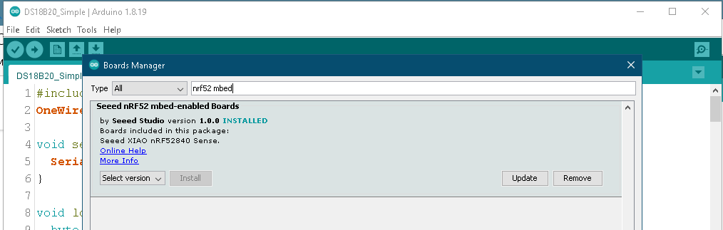
OneWire  ds(2);  // On pin 2 ---A 4.7K pullup resistor is required

Then I loaded board package 1.0.0 from the Board Manager’s “Seeed nRF52 mbed-enabled Boards” package, and selected the “Seeed nRF52840” board. (Doesn’t matter whether you select “Seeed nRF52840” or “Seeed nRF52840 Sense”)

You can try one of the other board options if you want, but I’m telling you what works for me. (See Footnote.)

Anyhow, output is now consistent with temperature measured at the DS18B20 with my handy-dandy GM320 Infrared Thermometer.

ROM = 28 5F 1 A8 2 0 0 23
  Chip = DS18B20
  Data = 1 DB 1 4B 46 7F FF 5 10 27  CRC=27
  Temperature = 29.69 Celsius, 85.44 Fahrenheit
No more addresses.

ROM = 28 5F 1 A8 2 0 0 23
  Chip = DS18B20
  Data = 1 DB 1 4B 46 7F FF 5 10 27  CRC=27
  Temperature = 29.69 Celsius, 85.44 Fahrenheit
No more addresses.
.
.   Etc.
.

Regards,

Dave

Footnote:
[/Begin Editorial Rant]
The XIAO BLE boards are terrific hardware items. Have used on a couple of experimental BLE projects. Not bad.
However…
The software is VERRRRRRRY Frustrating. Several releases that are, in some unpredictable, inexplicable, and inexcusable ways, incompatible. I wish Seeed would start all over. Make another board with these capabilities but give it another name. And don’t release a blasted bloomin’ thing until and unless SOMEONE would actually test the software and would publish examples that actually work “out of the box.” Life is simply too short to for some of us to keep dicking around with different versions that more-or-less work (mostly less).
[/End Editorial Rant]

2 Likes

I agree with you 1000% They would have a corner on the market if their software was at minimum tested, updated and maintained. Wishful thinking or sage business advice. They can decide.
I have put 6 months or more in the Xiao boards BLE and BLE Sense, That Nordic chip is very good…nRF52840. Great Boards as you say.
They seem to have too many items in the fire and it is starting to show. Great for prototypes but I would NEVER stake my product on it. too easy to roll your own now days. love the fitment though :smile:

it sounds like this is yet another issue with the XIAO nRF52 board library

there is a long thread somewhere in this forum about the XIAO nRF52’s deep sleep mode and the guys from (working at) Seeed suggested to revert to 1.0.0 version of the board lib. Same approach here – and good to know that OneWire works with that version.

But, again… it’s just that… the version 1.0.0 of their Board software is where some of the stuff works, but other (like me) have to use the latest version coz that is where the other/newer Libraries will only work.

Example: I needed the nRF52’s deep sleep and ArduinoBLE to work together. so I gave up – choosing to find an external solution on the power conservation and continued with using ArduinoBLE and the 2.x version of their Board.

I had the same problem. XIAO nRF52840 jammed every time I tried to use OneWire.h library.
Found today MaximWire that doesn’t need OneWire library. Got it via Library Manager
Example DiscoveryDevices.ino worked right a way.
MaximWire can also be found here in Github with examples: GitHub - adameat/MaximWire: MaximWire library for Arduino 33 BLE and DS18B20 sensor
Adding this line to other examples, they also started to work for me:
#define MAXIMWIRE_EXTERNAL_PULLUP
Without the line it looked like the bus pin stayd in input status, as it wasn’t able to pull the line down. Adding the line, the pin was able to drive the one wire bus.
Many thanks to ADAMEAT.

1 Like

hi i can make working in non mbed code with adafruit aproach just adding this line to example
#include “Adafruit_TinyUSB.h”
apperars adfruit resolves this issues but the seed not update new core updates form adafruit, can be good for final users if they can work together but looks more rival companies cheers this line fix alots of problems wiht others librarys too
#include “Adafruit_TinyUSB.h”
PD; anyway i install al nrf52 boards

Dear all,
after working some time with the classical OneWire and DallasTemperature Arduino lib the DS18B20 was not able to work poperly.
So I’ve installed the MaximWire lib at this repo:
https://github.com/adameat/MaximWire
and the sensor DS18B20 started to be seen immediately and the temperature measurements were correct. I’ve put a 4.7k resistor between the +3.3V and the data line of the sensor (yellow wire).

Here below my environment and setup.

Arduino IDE: 1.8.19
Board used: SEEED STUDIO XIAO nRF52840 sense

  • pin D2 used for the DS18B20 sensor
  • 4.7k resistor between +3.3V and pin D2

Boards definition files (use Board Manager):

  • Seed nRF52 Boards: version 1.0.0
  • Seed nRF52 mbed-enabled Boards: version 2.7.2

Library for manage OneWire (use Library Manager):

  • MaximWire: version 1.0.3

Include at the top of the sketch:

#define MAXIMWIRE_EXTERNAL_PULLUP
#include <MaximWire.h>
MaximWire::Bus bus(2);
MaximWire::DS18B20 sensTemp;
MaximWire::Address sensorAddr[3]; // I can use max 3 external sensor in my design increase it if you need more sensor to detect
int sens_idx = 0; // Used to store the number of detected sensors

into the Setup function you can use following code to discover the sensors and store relative address for future reference:

MaximWire::Discovery discovery = bus.Discover();
  do {
        MaximWire::Address address;
        if (discovery.FindNextDevice(address)) {
            Serial.print("FOUND: ");
            Serial.print(address.ToString());
            
            sensorAddr[sens_idx++] = address;

            if (address.IsValid()) {
                Serial.print(" (VALID) ");
            } else {
                Serial.print(" (INVALID)");
            }
            
            if (address.GetModelCode() == MaximWire::DS18B20::MODEL_CODE) {
                Serial.print(" (DS18B20)");
                MaximWire::DS18B20 sensTemp(address);
                if (sensTemp.IsParasitePowered(bus)) {
                    Serial.print(" (PARASITE POWER)");
                }
                float temp = sensTemp.GetTemperature<float>(bus);
                Serial.print(" temp=");
                Serial.print(temp);
                Serial.println();
                sensTemp.Update(bus);
            } else {
                Serial.println();
            }
        } else {
            Serial.println("NOTHING FOUND");
        }
    } while (discovery.HaveMore());
  Serial.println("DS18B20: Discovered " + String(sens_idx) + " temperature sensor(s)");

Into the main loop function, to read the sensors temperature:

            for (int idx=0; idx<sens_idx; idx++){
              MaximWire::Address address;
              address = sensorAddr[idx];
              if (address.GetModelCode() == MaximWire::DS18B20::MODEL_CODE) {
                MaximWire::DS18B20 sensTemp(address);
                float TempEstCelsius = sensTemp.GetTemperature<float>(bus);
                if (!isnan(TempEstCelsius)) {
                  String strTempEst = "DS18B20 #" + String(idx)+ ": " + String(TempEstCelsius,3);
                  Serial.println(strTempEst);
                }
                sensTemp.Update(bus);
              }
              else
              {
                Serial.println("DS18B20 ERROR : Could not read temperature data");
              }
            }

such code was adapted from the examples at the GitHub repo listed above.

Hope it can help someone and save some time!

Best regards.
Fire

1 Like

Hi there,
check this link, here… demo the DS18B20 working in the B-roll. so see it there.
Here is the code I used in the demo.

/**************************************************************************
 This is an example of the Cheepest OLEDs based on SSD1306 & a DS18B20 Temp sensor.
 connected to a grove Expansion Board.

 Pick one up today in the adafruit shop!
 ------> http://www.adafruit.com/category/63_98

 This example is for a 128x32 pixel display using I2C to communicate
 3 pins are required to interface (two I2C and one reset).

/**************************************************************************/
#include <Arduino.h>
#include <SPI.h>
#include <Wire.h>
#include <Adafruit_GFX.h>
#include <Adafruit_SSD1306.h>
#include <OneWire.h>
#include <DallasTemperature.h>
//#include <Fonts/FreeSerif12pt7b.h>
//#include <Fonts/FreeSerif9pt7b.h>

#define ONE_WIRE_BUS D7
OneWire oneWire(ONE_WIRE_BUS);
DallasTemperature DS18B20(&oneWire);

#define SCREEN_WIDTH 128 // OLED display width, in pixels
#define SCREEN_HEIGHT 32 // OLED display height, in pixels
// Define monochrome graphics:
static const unsigned char PROGMEM _error [] = {
0x00, 0x00, 0x00, 0x00, 0x00, 0x3F, 0xFC, 0x00, 0x00, 0xE0, 0x07, 0x00, 0x01, 0x80, 0x01, 0x80,
0x06, 0x00, 0x00, 0x60, 0x0C, 0x00, 0x00, 0x30, 0x08, 0x01, 0x80, 0x10, 0x10, 0x03, 0xC0, 0x08,
0x30, 0x02, 0x40, 0x0C, 0x20, 0x02, 0x40, 0x04, 0x60, 0x02, 0x40, 0x06, 0x40, 0x02, 0x40, 0x02,
0x40, 0x02, 0x40, 0x02, 0x40, 0x02, 0x40, 0x02, 0x40, 0x02, 0x40, 0x02, 0x40, 0x02, 0x40, 0x02,
0x40, 0x02, 0x40, 0x02, 0x40, 0x02, 0x40, 0x02, 0x40, 0x03, 0xC0, 0x02, 0x40, 0x01, 0x80, 0x02,
0x40, 0x00, 0x00, 0x02, 0x60, 0x00, 0x00, 0x06, 0x20, 0x01, 0x80, 0x04, 0x30, 0x03, 0xC0, 0x0C,
0x10, 0x03, 0xC0, 0x08, 0x08, 0x01, 0x80, 0x10, 0x0C, 0x00, 0x00, 0x30, 0x06, 0x00, 0x00, 0x60,
0x01, 0x80, 0x01, 0x80, 0x00, 0xE0, 0x07, 0x00, 0x00, 0x3F, 0xFC, 0x00, 0x00, 0x00, 0x00, 0x00
};

// Define the data holders:
//float t = m_temperature;
float temps, m_temperature;
int class_number = 0;
long timer;
uint16_t error;
char errorMessage[256];
// Declaration for an SSD1306 display connected to I2C (SDA, SCL pins)
#define OLED_RESET     -1 // Reset pin # (or -1 if sharing Arduino reset pin)
#define SCREEN_ADDRESS 0x3C ///< See datasheet for Address; 0x3D for 128x64, 0x3C for 128x32
Adafruit_SSD1306 display(SCREEN_WIDTH, SCREEN_HEIGHT, &Wire, OLED_RESET);

#define NUMFLAKES     10 // Number of snowflakes in the animation example
#define LOGO_HEIGHT   12
#define LOGO_WIDTH    12
static const unsigned char PROGMEM logo_bmp[] =
{ 0b00000000, 0b11000000,
  0b00000001, 0b11000000,
  0b00000001, 0b11000000,
  0b00000011, 0b11100000,
  0b11110011, 0b11100000,
  0b11111110, 0b11111000,
  0b01111110, 0b11111111,
  0b00110011, 0b10011111,
  0b00011111, 0b11111100,
  0b00001101, 0b01110000,
  0b00011011, 0b10100000,
  0b00111111, 0b11100000,
  0b00111111, 0b11110000,
  0b01111100, 0b11110000,
  0b01110000, 0b01110000,
  0b00000000, 0b00110000 };

const int buttonPin = 2;     // the number of the pushbutton pin
int buttonState = 0;          // variable for reading the pushbutton status
uint8_t binterruptCount = 0;  // Amount of received interrupts
const int BuzzerPin = 0;
int buzzer = BuzzerPin;
#define LEDR LED_BUILTIN  // default
#define LEDG LED_GREEN
#define LEDB LED_BLUE
uint8_t interruptCount = 0;      // Amount of received interrupts
uint8_t prevInterruptCount = 0;  // Interrupt Counter from last loop
bool first10LoopCompleted = false;
int deviceCount = 0; // variable to store the number of devices connected
DeviceAddress deviceAddress; // variable to store the device address


void setup() {
  Wire.begin();
  delay(250);
    Serial.begin(9600);
  delay(2000);
  DS18B20.begin();
 
  //while (!Serial) delay(2100);      // Code will wait until USB port is plugged in.
  pinMode(BuzzerPin, OUTPUT);
  buzzer = LOW ;  // Buzzer OFF
  Serial.println();
  Serial.println("Program " __FILE__ " compiled on " __DATE__ " at " __TIME__);
  Serial.println();
  Serial.println("Processor came out of reset.");
  Serial.println();
  //pinMode(D7, INPUT);  //  Ds180
 delay (500);
// Locate the devices on the bus:
  Serial.println("Locating devices...");
  Serial.print("Found ");
  deviceCount = DS18B20.getDeviceCount();
  Serial.print(deviceCount);
  Serial.println(" devices");

  Serial.println("Printing addresses...");
  for (int i = 0;  i < deviceCount;  i++) {
    Serial.print("Sensor ");
    Serial.print(i + 1);
    Serial.print(" : ");
    DS18B20.getAddress(deviceAddress, i);
    printAddress(deviceAddress);
  }
  
  // SSD1306_SWITCHCAPVCC = generate display voltage from 3.3V internally
  if(!display.begin(SSD1306_SWITCHCAPVCC,  0x3C)) {
    Serial.println(F("SSD1306 allocation failed"));
    for(;;); // Don't proceed, loop forever
  }
  display.display();
  delay(2000); // Pause for 2 seconds
  // Clear the buffer
  display.clearDisplay();
  // Draw a single pixel in white
  display.drawPixel(10, 10, SSD1306_WHITE);
  // Show the display buffer on the screen. You MUST call display() after
  // drawing commands to make them visible on screen!
  display.display();
  delay(1000);
  
  //testdrawchar();      // Draw characters of the default font

  //testdrawstyles();    // Draw 'stylized' characters

  testscrolltext();    // Draw scrolling text

  testdrawbitmap();    // Draw a small bitmap image

  // Invert and restore display, pausing in-between
  display.invertDisplay(true);
  delay(500);
  display.invertDisplay(false);
  delay(500);

  //testanimate(logo_bmp, LOGO_WIDTH, LOGO_HEIGHT); // Animate bitmaps

mTemperature();

}


void loop() {
  testscrolltext();    // Draw scrolling text
  delay (2000);
  mTemperature();
   delay (3000);
}

void mTemperature(){
  
  // Obtain the temperature measurement generated by the DS18B20 Waterproof Temperature Sensor.
  DS18B20.setResolution(10);
  DS18B20.requestTemperatures(); 
  float ctemp = DS18B20.getTempCByIndex(0);
  m_temperature = DS18B20.getTempFByIndex(0);
  Serial.print("\n Temperature: "); Serial.print(m_temperature); Serial.println("°F");
  delay(250);
  display.clearDisplay(); // Clear display buffer
  display.setTextSize(1);       // Normal 1:1 pixel scale
  display.setTextColor(WHITE);  // Draw white text
  display.setCursor(0, 0);      // Start at top-left corner
  display.display();
  display.print("TEMP is:\n");  //Flash Test:0123456789
    display.setTextSize(3);
  display.print(m_temperature); 
  display.setTextSize(1);
    display.print("F");
    display.display();
  delay(1100);

}
void printAddress(DeviceAddress deviceAddress) {
  for (uint8_t i = 0; i < 8; i++) {
    Serial.print("0x");
    if (deviceAddress[i] < 0x10) {
      Serial.print("0");
    }
    Serial.print(deviceAddress[i], HEX);
    if (i < 7) {
      Serial.print(", ");
    }
  }
  Serial.println(" done...");
}

void testdrawchar(void) {
  display.clearDisplay();
  display.setTextSize(1);      // Normal 1:1 pixel scale
  display.setTextColor(SSD1306_WHITE); // Draw white text
  display.setCursor(0, 0);     // Start at top-left corner
  display.cp437(true);         // Use full 256 char 'Code Page 437' font

  // Not all the characters will fit on the display. This is normal.
  // Library will draw what it can and the rest will be clipped.
  for(int16_t i=0; i<128; i++) {
    if(i == '\n') display.write(' ');
    else          display.write(i);
  }

  display.display();
  delay(1000);
}
void err_msg(){
  // Show the error message on the SSD1306 screen.
  display.clearDisplay();   
  display.drawBitmap(48, 0, _error, 32, 32, SSD1306_WHITE);
  display.setTextSize(1); 
  display.setTextColor(SSD1306_WHITE);
  display.setCursor(0,40); 
  display.println("Check the serial monitor to see the error!");
  display.display();  
}

void testdrawstyles(void) {
  display.clearDisplay();
  display.setTextSize(1);             // Normal 1:1 pixel scale
  display.setTextColor(SSD1306_WHITE);        // Draw white text
  display.setCursor(0,0);             // Start at top-left corner
  display.println(F("Hello, DUDE!! "));
  display.setTextColor(SSD1306_BLACK, SSD1306_WHITE); // Draw 'inverse' text
  display.println(3.141592);
  display.setTextSize(2);             // Draw 2X-scale text
  display.setTextColor(SSD1306_WHITE);
  display.print(F("0x")); display.println(0xDEADBEEF, HEX);
  display.display();
  delay(500);
}

void testscrolltext(void) {
  display.clearDisplay();
  display.setTextSize(1); // Draw 2X-scale text
  display.setTextColor(SSD1306_WHITE);
  display.setCursor(10, 0);
  display.print(F("Temp Is\n"));
  display.display();      // Show initial text
  delay(100);
  // Scroll in various directions, pausing in-between:
  display.startscrollright(0x00, 0x0F);
  delay(2300);
  display.stopscroll();
  delay(200);
  display.startscrollleft(0x00, 0x0F);
  delay(2500);
  display.stopscroll();
  display.setTextColor(SSD1306_BLACK);
  display.setCursor(10, 0);
  display.print("Temp Is");
  display.display();      // Show initial text
  delay(300);
  display.setTextColor(SSD1306_WHITE);
  display.setTextSize(2);             // Draw 2X-scale text
  display.setCursor(0, 10);
  float ctemp = DS18B20.getTempFByIndex(0);
  delay(250);
  display.print(ctemp);
  display.print(" ");
  display.setTextSize(1);
  display.print("F");
  delay(2000);
  display.display();
  delay(2000);
  display.startscrolldiagright(0x00, 0x07);
  delay(2000);
  display.startscrolldiagleft(0x00, 0x07);
  delay(2000);
  display.stopscroll();
  delay(2000);
}

void testdrawbitmap(void) {
  display.clearDisplay();

  display.drawBitmap(
    (display.width()  - LOGO_WIDTH ) / 2,
    (display.height() - LOGO_HEIGHT) / 2,
    logo_bmp, LOGO_WIDTH, LOGO_HEIGHT, 1);
  display.display();
  delay(1000);
}

#define XPOS   0 // Indexes into the 'icons' array in function below
#define YPOS   1
#define DELTAY 2

void testanimate(const uint8_t *bitmap, uint8_t w, uint8_t h) {
  int8_t f, icons[NUMFLAKES][3];

  // Initialize 'snowflake' positions
  for(f=0; f< NUMFLAKES; f++) {
    icons[f][XPOS]   = random(1 - LOGO_WIDTH, display.width());
    icons[f][YPOS]   = -LOGO_HEIGHT;
    icons[f][DELTAY] = random(1, 6);
    Serial.print(F("x: "));
    Serial.print(icons[f][XPOS], DEC);
    Serial.print(F(" y: "));
    Serial.print(icons[f][YPOS], DEC);
    Serial.print(F(" dy: "));
    Serial.println(icons[f][DELTAY], DEC);
  }

  for(;;) { // Loop forever...
    display.clearDisplay(); // Clear the display buffer

    // Draw each snowflake:
    for(f=0; f< NUMFLAKES; f++) {
      display.drawBitmap(icons[f][XPOS], icons[f][YPOS], bitmap, w, h, SSD1306_WHITE);
    }

    display.display(); // Show the display buffer on the screen
    delay(200);        // Pause for 1/10 second

    // Then update coordinates of each flake...
    for(f=0; f< NUMFLAKES; f++) {
      icons[f][YPOS] += icons[f][DELTAY];
      // If snowflake is off the bottom of the screen...
      if (icons[f][YPOS] >= display.height()) {
        // Reinitialize to a random position, just off the top
        icons[f][XPOS]   = random(1 - LOGO_WIDTH, display.width());
        icons[f][YPOS]   = -LOGO_HEIGHT;
        icons[f][DELTAY] = random(1, 6);
      }
    }
  }
}

Hope That Helps :slight_smile: GL , PJ :v:

here is Compiler output

FQBN: Seeeduino:nrf52:xiaonRF52840Sense
Using board 'xiaonRF52840Sense' from platform in folder: C:\Users\Dude\AppData\Local\Arduino15\packages\Seeeduino\hardware\nrf52\1.1.8
Using core 'nRF5' from platform in folder: C:\Users\Dude\AppData\Local\Arduino15\packages\Seeeduino\hardware\nrf52\1.1.8
edit----for Brevity----
Zip created at C:\Users\Dude\AppData\Local\Temp\arduino\sketches\CC942BAF52BC74DA90551B61D261992E/Display_DS18B20_SSD1306_DEMO.ino.zip
Multiple libraries were found for "Adafruit_TinyUSB.h"
  Used: D:\Arduino_projects\libraries\Adafruit_TinyUSB_Library
  Not used: C:\Users\Dude\AppData\Local\Arduino15\packages\Seeeduino\hardware\nrf52\1.1.8\libraries\Adafruit_TinyUSB_Arduino
Using library SPI at version 1.0 in folder: C:\Users\Dude\AppData\Local\Arduino15\packages\Seeeduino\hardware\nrf52\1.1.8\libraries\SPI 
Using library Wire at version 1.0 in folder: C:\Users\Dude\AppData\Local\Arduino15\packages\Seeeduino\hardware\nrf52\1.1.8\libraries\Wire 
Using library Adafruit GFX Library at version 1.11.9 in folder: D:\Arduino_projects\libraries\Adafruit_GFX_Library 
Using library Adafruit BusIO at version 1.16.1 in folder: D:\Arduino_projects\libraries\Adafruit_BusIO 
Using library Adafruit SSD1306 at version 2.5.10 in folder: D:\Arduino_projects\libraries\Adafruit_SSD1306 
Using library OneWire at version 2.3.8 in folder: D:\Arduino_projects\libraries\OneWire 
Using library DallasTemperature at version 3.9.0 in folder: D:\Arduino_projects\libraries\DallasTemperature 
Using library Adafruit TinyUSB Library at version 3.1.5 in folder: D:\Arduino_projects\libraries\Adafruit_TinyUSB_Library 
"C:\\Users\\Dude\\AppData\\Local\\Arduino15\\packages\\Seeeduino\\tools\\arm-none-eabi-gcc\\9-2019q4/bin/arm-none-eabi-size" -A "C:\\Users\\Dude\\AppData\\Local\\Temp\\arduino\\sketches\\CC942BAF52BC74DA90551B61D261992E/Display_DS18B20_SSD1306_DEMO.ino.elf"
Sketch uses 71392 bytes (8%) of program storage space. Maximum is 811008 bytes.
Global variables use 8564 bytes (3%) of dynamic memory, leaving 229004 bytes for local variables. Maximum is 237568 bytes.

Thanks!
Unfortunately this is not able to work on my side, do not know if may be important, for the data connection of the sensor I’m using the pin D2.

#define ONE_WIRE_BUS D2
OneWire oneWire(ONE_WIRE_BUS);

All the other libraries version are same your (OneWire 2.3.8 and DallasTemperature 3.9.0).

So, at this time and at least for me, the only way is to use the MaximWire library (I’m currently using the 1.0.3 version). With this one no trouble arise at first attempt. I think that should be mainly a timing issue on these different lib and the hardware I’m currently using. I’ve to take a deeper look to the data signal with oscilloscope, but at a first look it seems such type of problem.

I didnt know adafruit sold grove gear…

what is the purpose of using these “non-standard” libs

Hi there,
2 things, The delay’s are needed…
Can you post the code your using, the snips are incomplete.
HTH
GL :slight_smile: PJ

D2 does work also. :v:

@PJ_Glasso
Here in attchment my full design, it have many things bca I’m doing a preliminary testing about the module.
Here an example of the output when the module is connected by a central device (I’m using an Android phone and the nRF Connect app installed through the Play Store)

INFO BLE: RSSI = -58
Acc: 0.191;0.849;0.469
Gyr: 1.050;-2.870;0.210
Temp: 26.82
AnIn0: 1633.081
DS18B20 #0: 28.438

leds are blinking at different rate as specified into the source code.

Next step is to set tx power to +8dbm, do you have some suggest?
Thanks and best regards!
Fire
xiao_nrf52840_test.zip (3,6 KB)

Hi there,
Good stuff for sure.
the IMU temp is a little , funny I have found. based on where the IMU is under the LID.
more of an internal reading IMO, I use it just to see if the hardware is alive.
The examples show the delay as well , I believe it is needed between readings for settle time.
NOT ideal but add some delay to test if it is the effect I think it is.
HTH
GL :slight_smile: PJ

also I like the Nrf_dongle for $9 bucs make BLE testing and trouble shooting a breeze the NRF_connect for desktop is the truth IMO.

@PJ_Glasso
Hi thanks!
Have you did some testing about SAADC with double buffering through PPI settings and related timer attached to perform DMA buffer update after the sampling completed?

I’m looking to implement such way to perform some real time signal anaysis with the XIAO nRF52840 sense board.

At now the only timer usable looks to me Timer3 or Timer4 because:

  • Timer0 : used by sofdevice s140 (I need to use also BLE)
  • Timer1 : from my understanding it is used by Mbed OS
  • Timer2 : if I’m right it is used by the ArduinoBLE (should it based on ble cordio)

In your perspective I’m right about above considerations?

BR
Fire

Hi there,
Yes, Only timer 3 or 4 can be used as the T1 is used internal.
There is another Library to try also.
To do DMA though it’s not needed just the pointer is. It does work.
search the threads there’s one that addresses it.
HTH
GL :slight_smile: PJ
:v: