

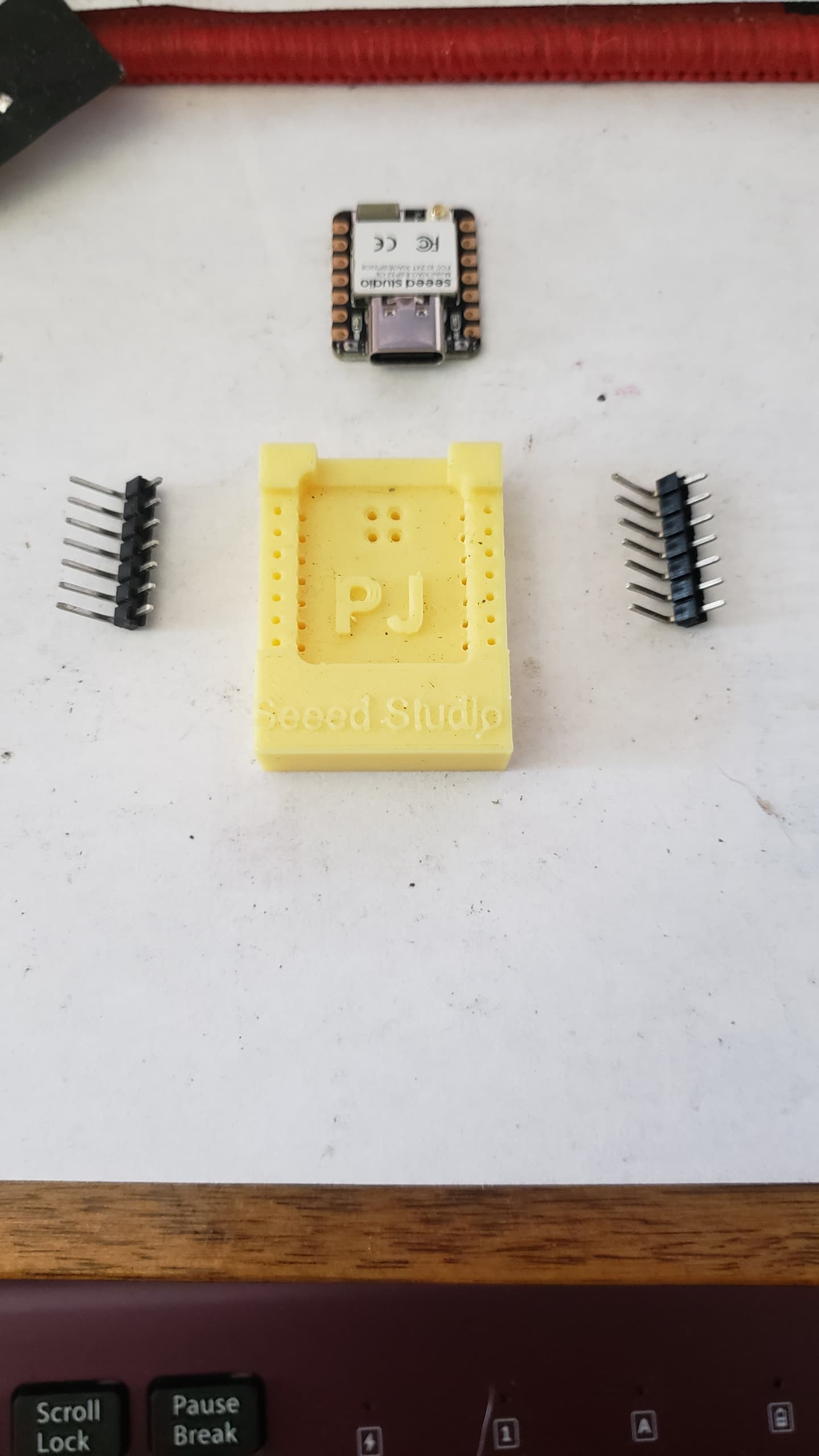
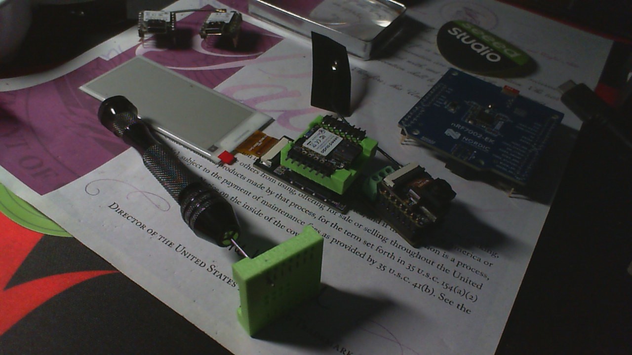
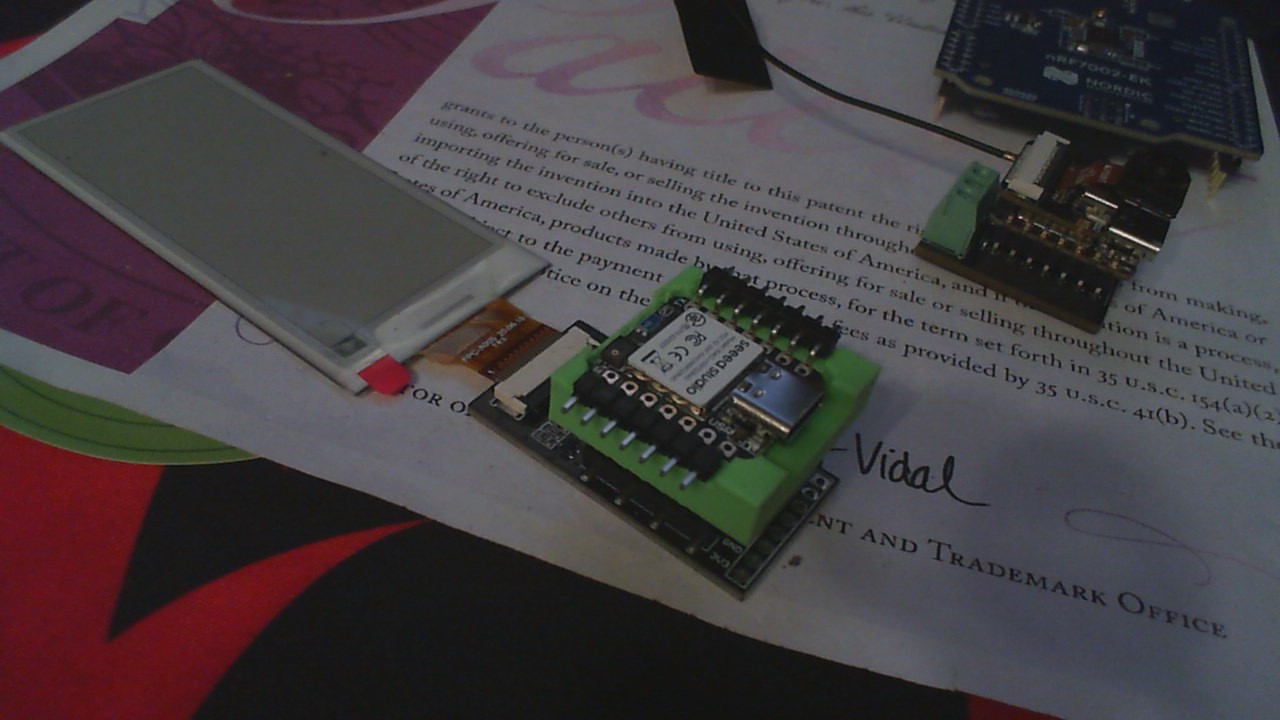
A truly solderless socket for testing Castellated PCB micro controllers like the SeeedStudio Xiao Nrf52840, my First crack was fashioned after Rizo’s ESP32 Sockets, Very cool. No pins to bend with this one, just print and add a few pieces of the hardware pin sets. You can add the pogos as I did for connection to the debug pins on the dev board. NO more soldering and unsoldering the PCB’s until final assembly. ;-p files are up on Thingiverse
enjoy.
Revision II video.Thingiverse files
GL :-p

Where did you get the right angle hardware pin sets?
LOL, You READY…
I bent some straight ones…
HTH
GL ![]()
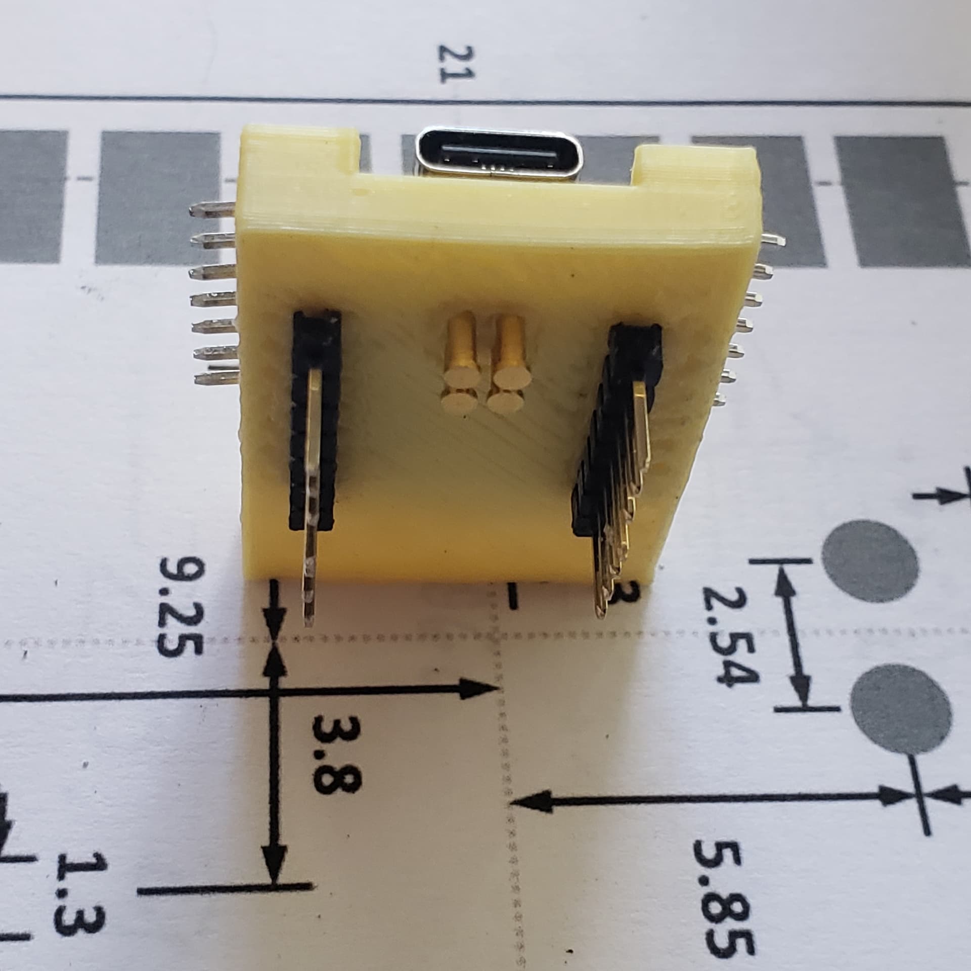
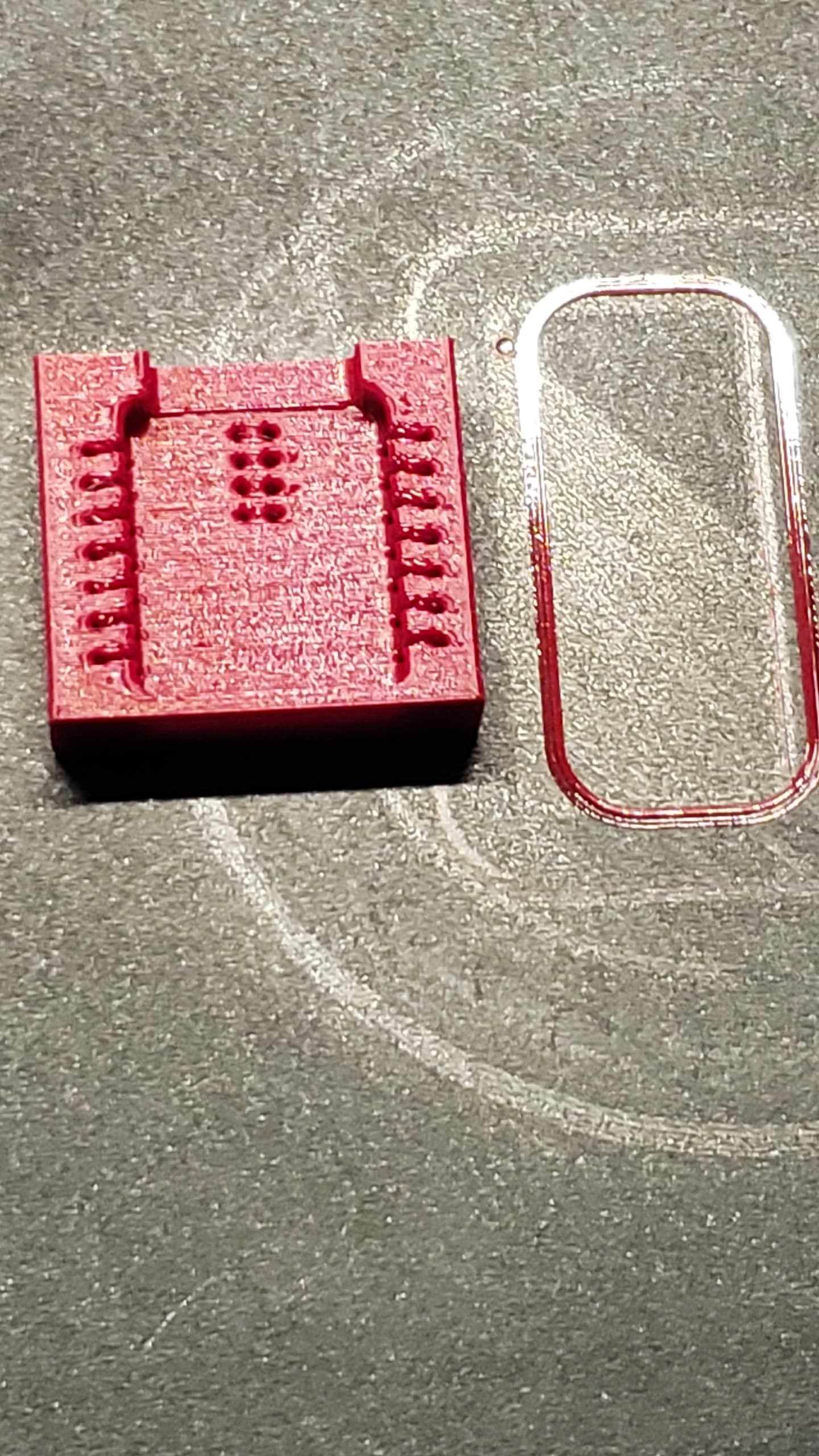
and BTW It’s two sets one from the top and one set on the bottom, if you can’t find longer ones or pre bent set’s. ![]() Everything is pressure fit too, see the video of how if you get it correct it snaps into the socket Ship, Shape like.
Everything is pressure fit too, see the video of how if you get it correct it snaps into the socket Ship, Shape like.
Thanks for sharing this design!
What are the dimensions of the pogo pins you used for this? Could you link the specific product you used?
Another question: what is the purpose of the second set of headers which insert from below and don’t make electrical contact with any of the pins on the Xiao? Are they just for easy mounting on a breadboard?
Hi there,
Yes they do,(drill them thru) the pogo’s will depend on the thickness of the socket.
the right angle (bent headers) overlap and touch the tops of the straight set.
It’s a WIP, so the dimensions have change slightly , mostly to make it skinnier and thinner and a notch in the rear for room for the Antenna on the ESP series chips. Also adding the connections to the battery pads on the bottom so REV3 is on the drawing board.
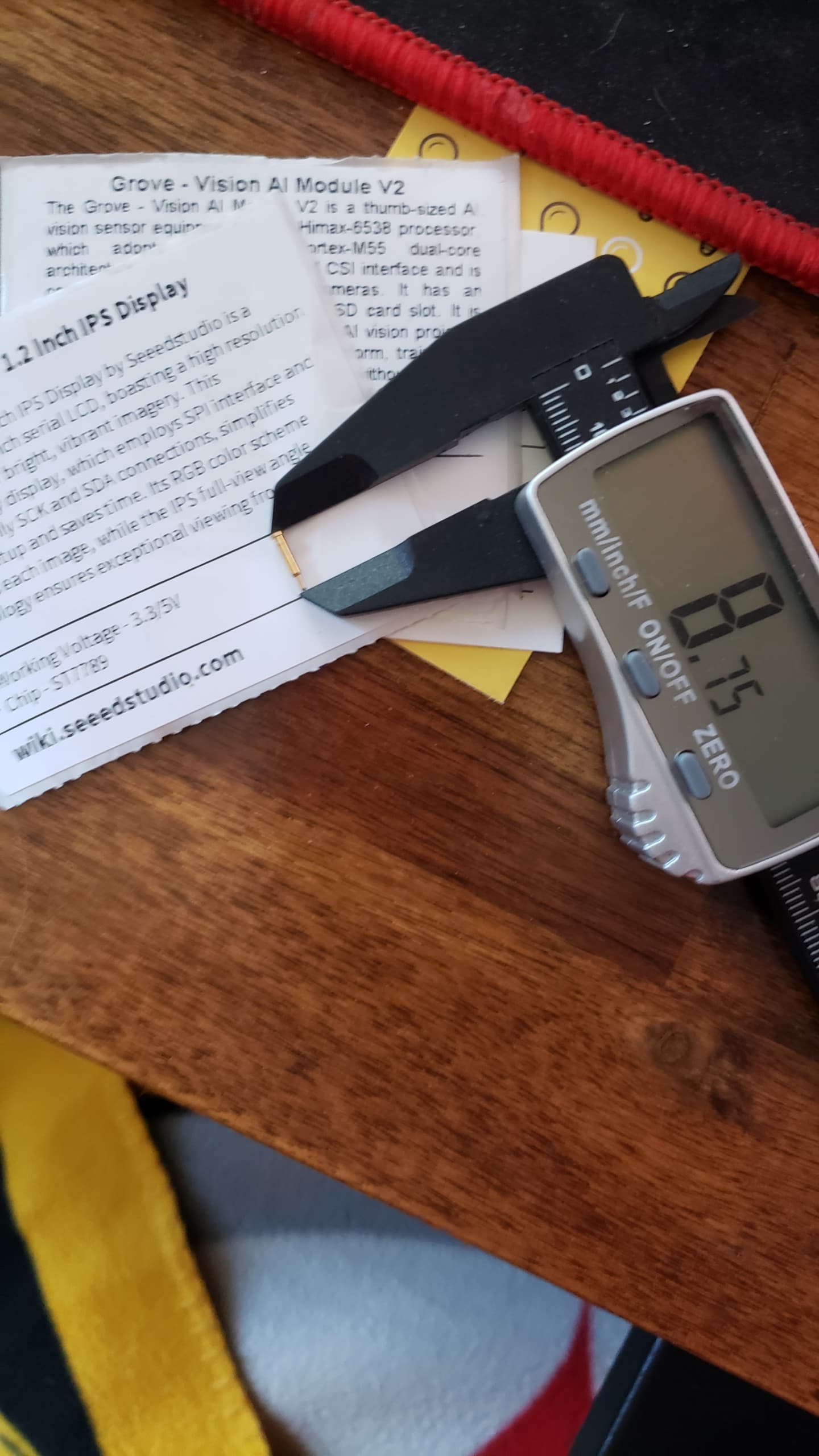
Pogo’s come in basically two styles, Flat bottom and Board mount.
sizes this one is 8.75mm (I recommend get a few bigger and smaller) they only cost a couple bucs, but the shipping is more, LOL so wait and order a few things to make it worth the freight IMO.
HTH
GL
Time is tight these days, I’ll tweak and upload a fresh model to thingiverse with aforementioned enhancements asap. ![]()
That makes sense, thanks!
It looks like the FreeCAD file on the REV2 Thingiverse page is for an older revision of the part. Do you mind uploading the latest FreeCAD file?
I’ve run into a couple issues with this breakout board:
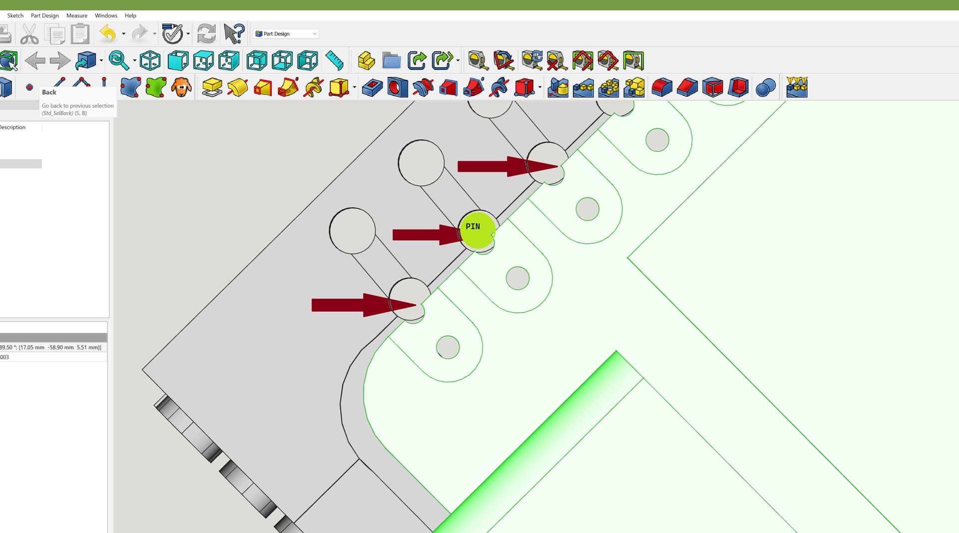
- The debug pogo pins seem to be in the wrong spot? They don’t seem to be making an electrical connection. I think they need to be moved about 0.9 mm up (i.e. in the direction of the USB-C port).
- The holes that the bent pins go into are too small (they’re smaller than the other set of “mounting” pin holes).
I’d be happy to help fix these issues if you could upload a new version of the file ![]()
I’ll be updating soon , the files on thingeverse ![]()
testing , for testing…
HTH
GL ![]() PJ
PJ

Hi there,
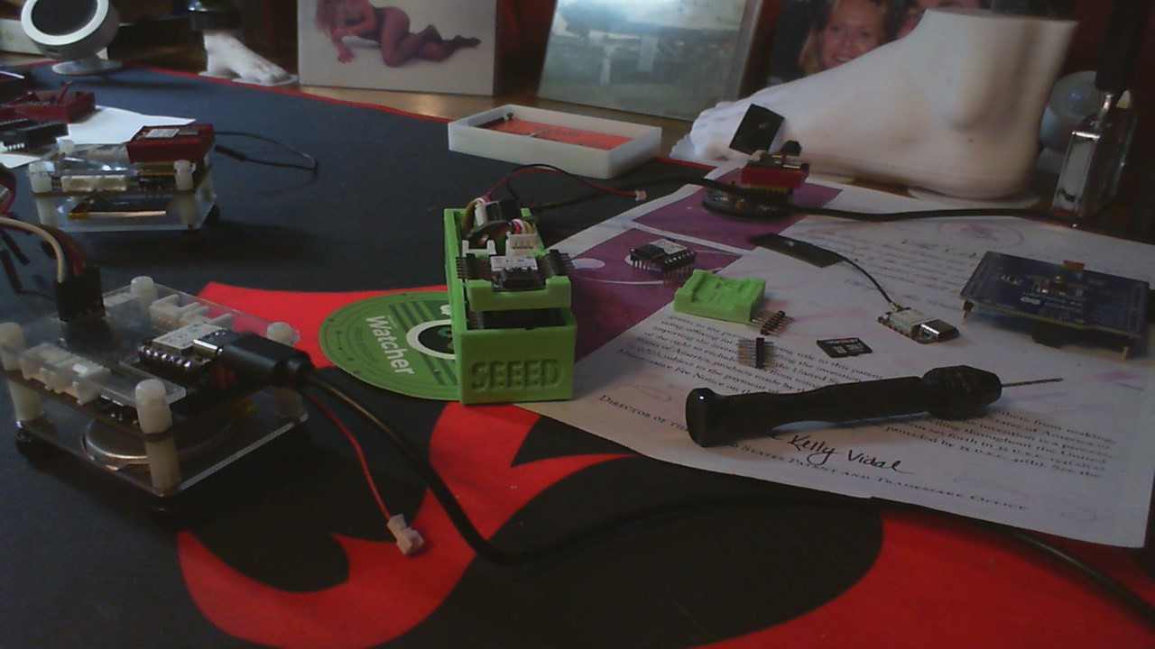
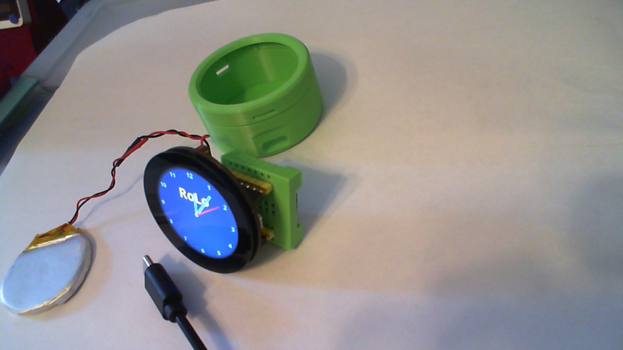
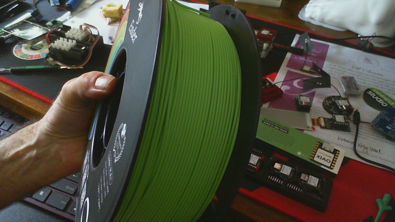
Got that Sweet Seeed Green PLA+ the other day and my , my the Green is anything but mean…
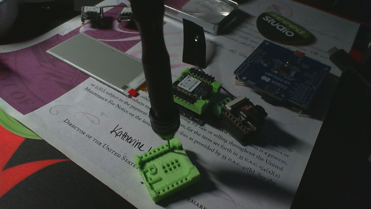
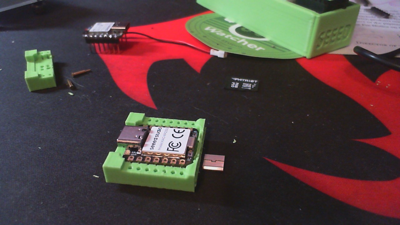
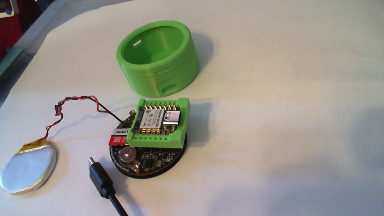
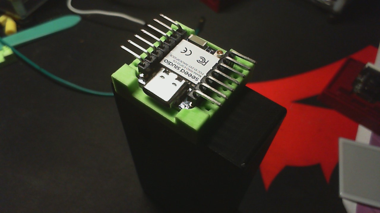
Printed a C6 socket and tested it with a Nrf52840 also. 8 pogo’s too.
Lowered the back with the wording to accommodate the antenna.
Enjoy and The G.gode is in the ZIP.

GL ![]() PJ
PJ ![]()
Enjoy
XiAO_C6_Socket.zip (198.0 KB)
I also use this .90 hand-drill and bit to dress the small holes so the fit of header pins is loose or tight.
YMMV
That Sexy Seeed Green…

Should be on the website for sale.
in the future some clamp arm or screw to hold the pressure down?
Hi there,
Merry Christmas ![]()
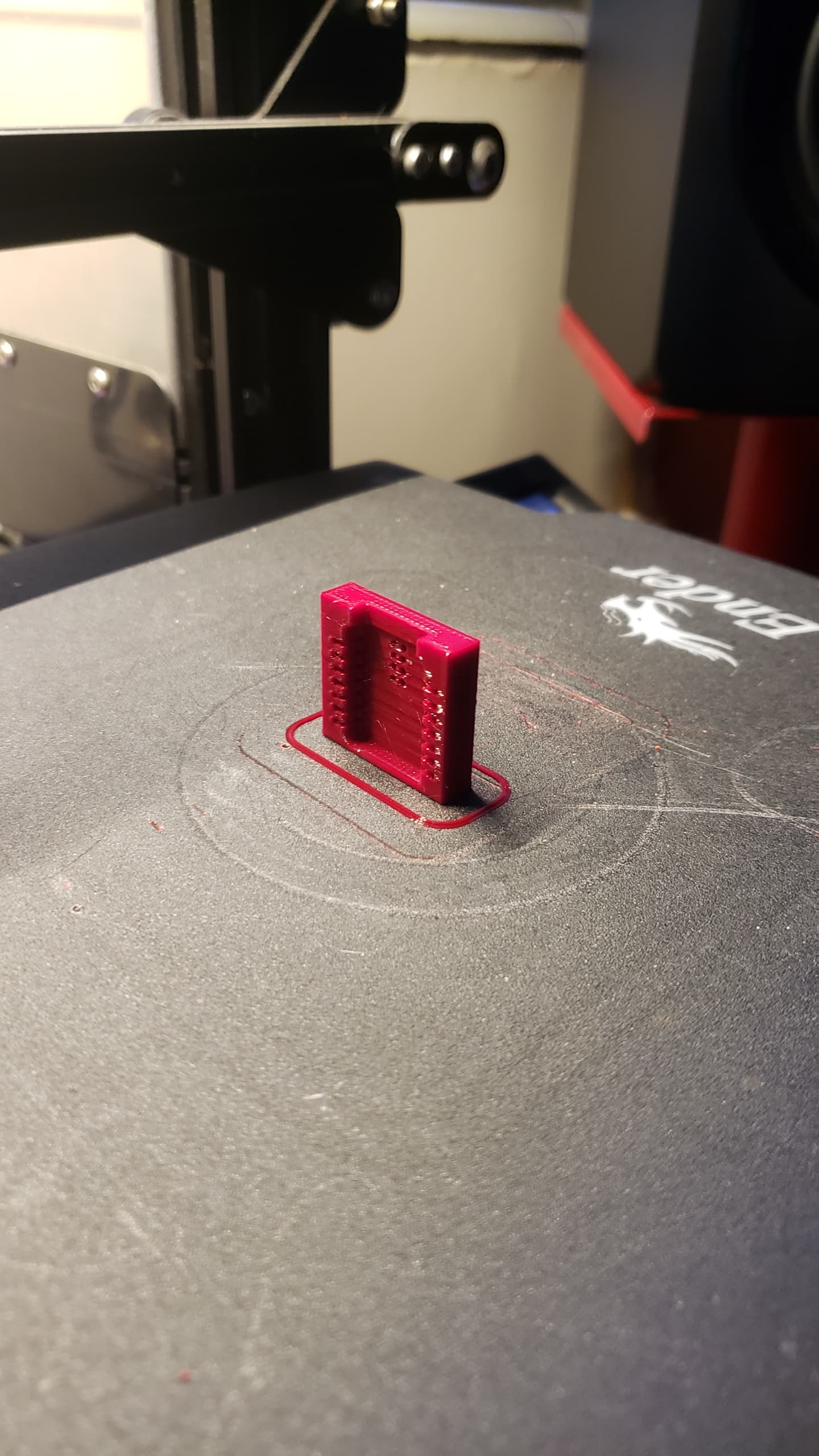
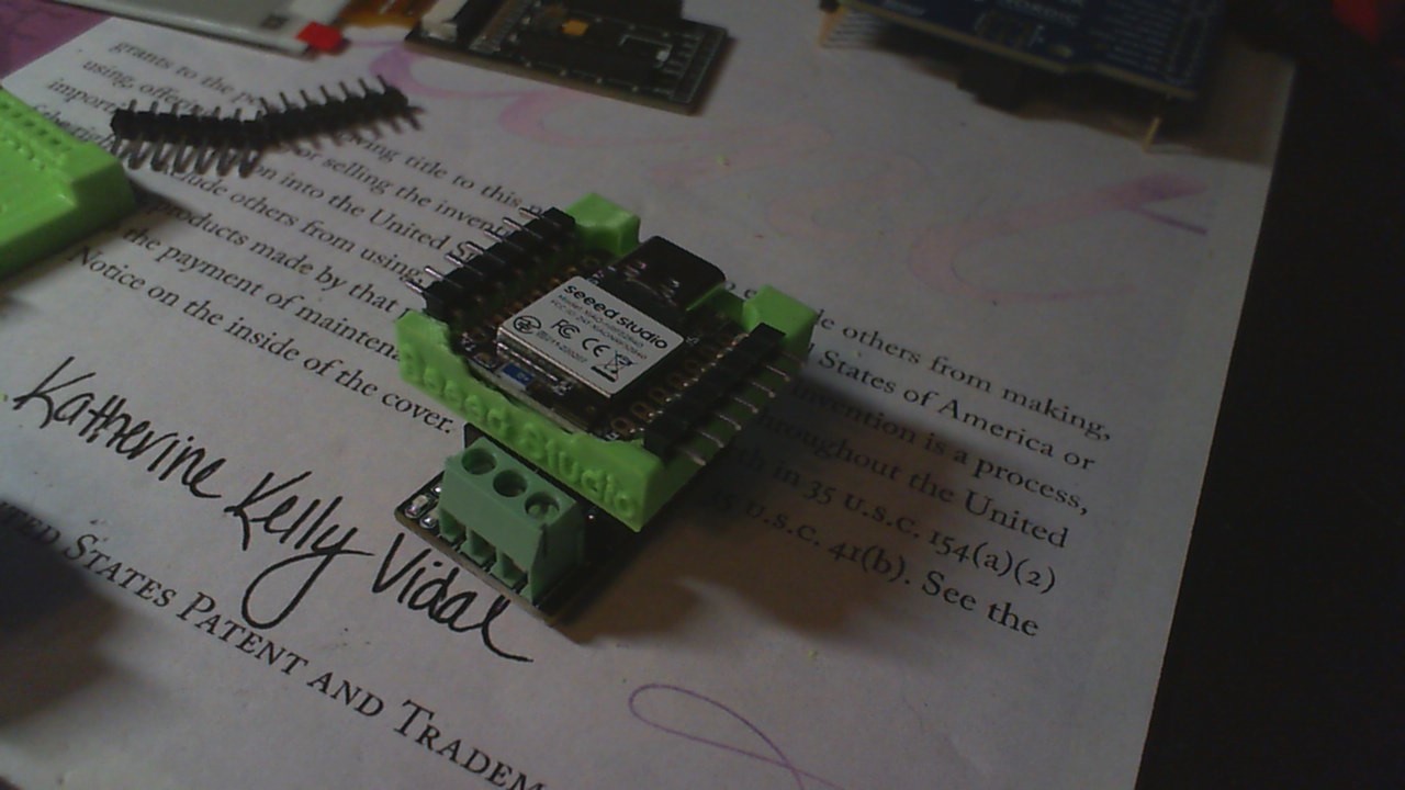
The final release of the socket for Xiao, This one is without Initials and fits or seats all the different Xiao’s Print your own and add the style of pins you like, you see it in several latest videos and it holds the Xiao with a friction fit, properly seated nothing else is needed. Pins can be inserted as you see from the top or from the bottom, straight or Bent(gaulwing) so as to easily attach test leads or jumpers (female) on the ends. The G-code and STL are attached as a GIVE-BACK to those who have helped ,shared, and contributed. ![]()
GL ![]() PJ
PJ ![]()
XiAO_Cut_Socket_ALL.zip (152.5 KB)


Hi there,
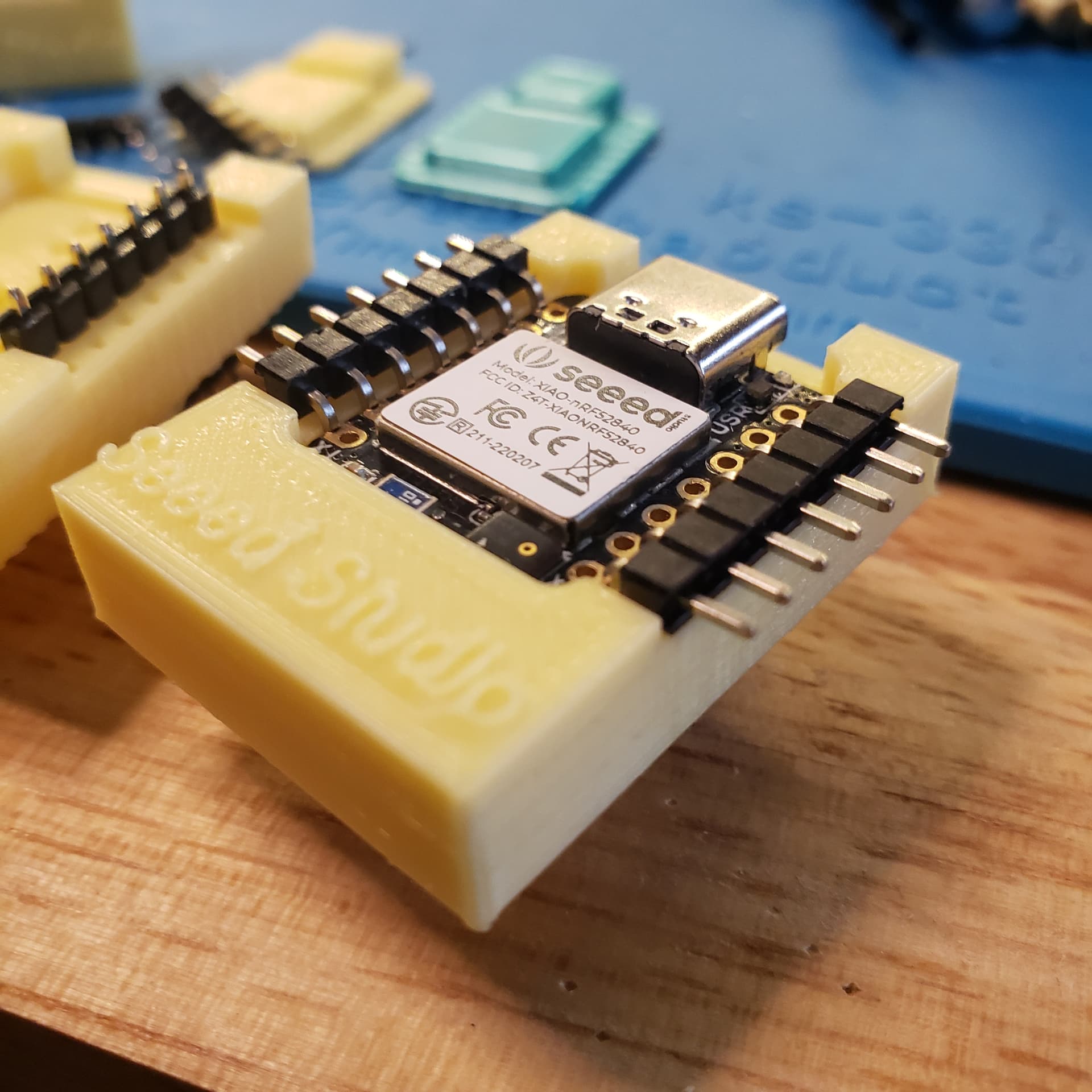
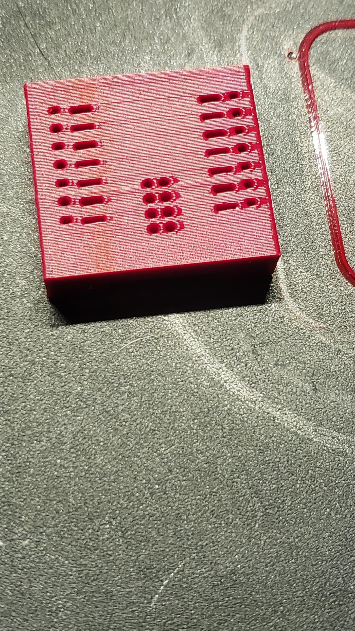
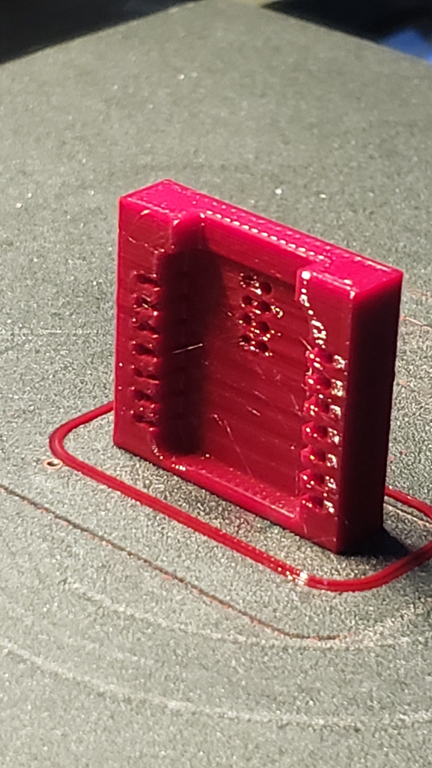
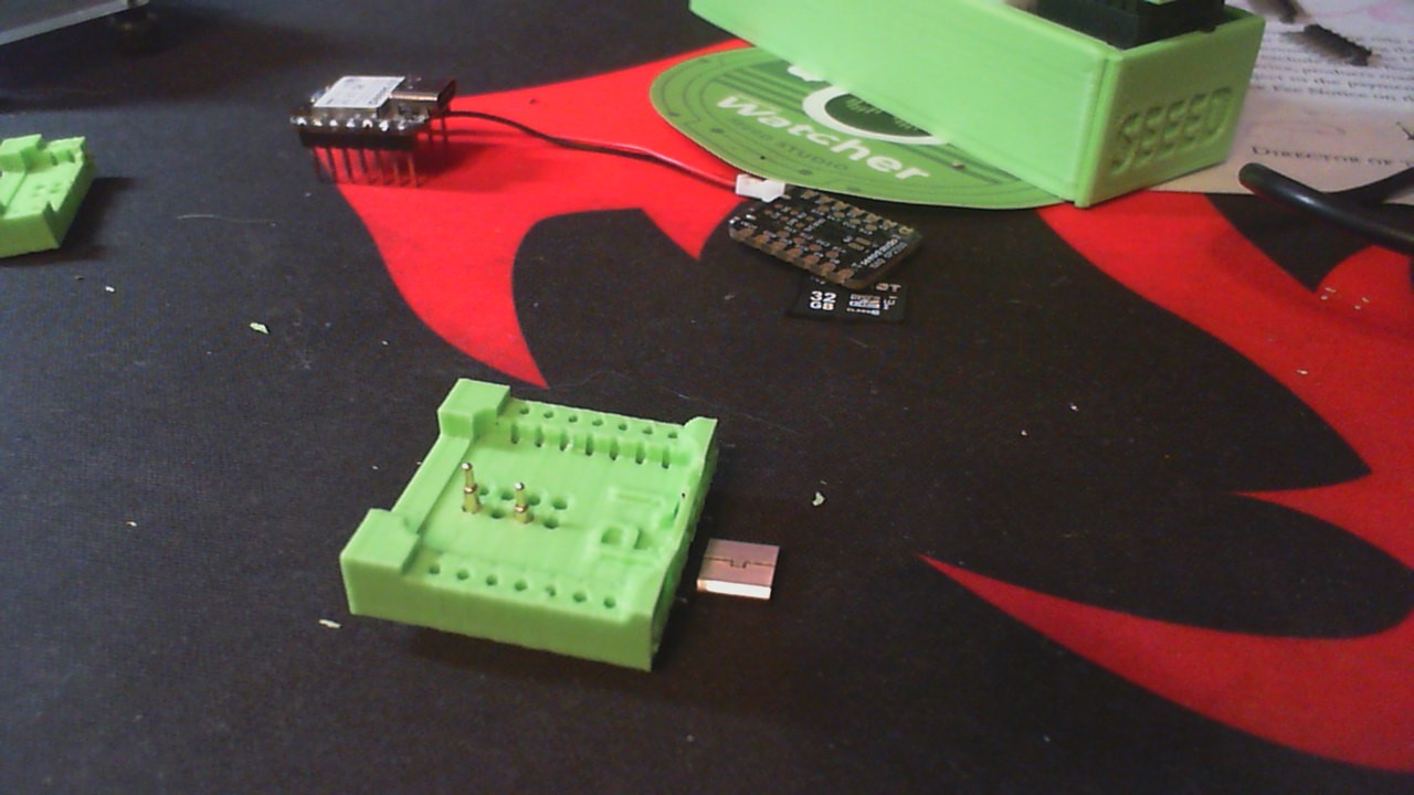
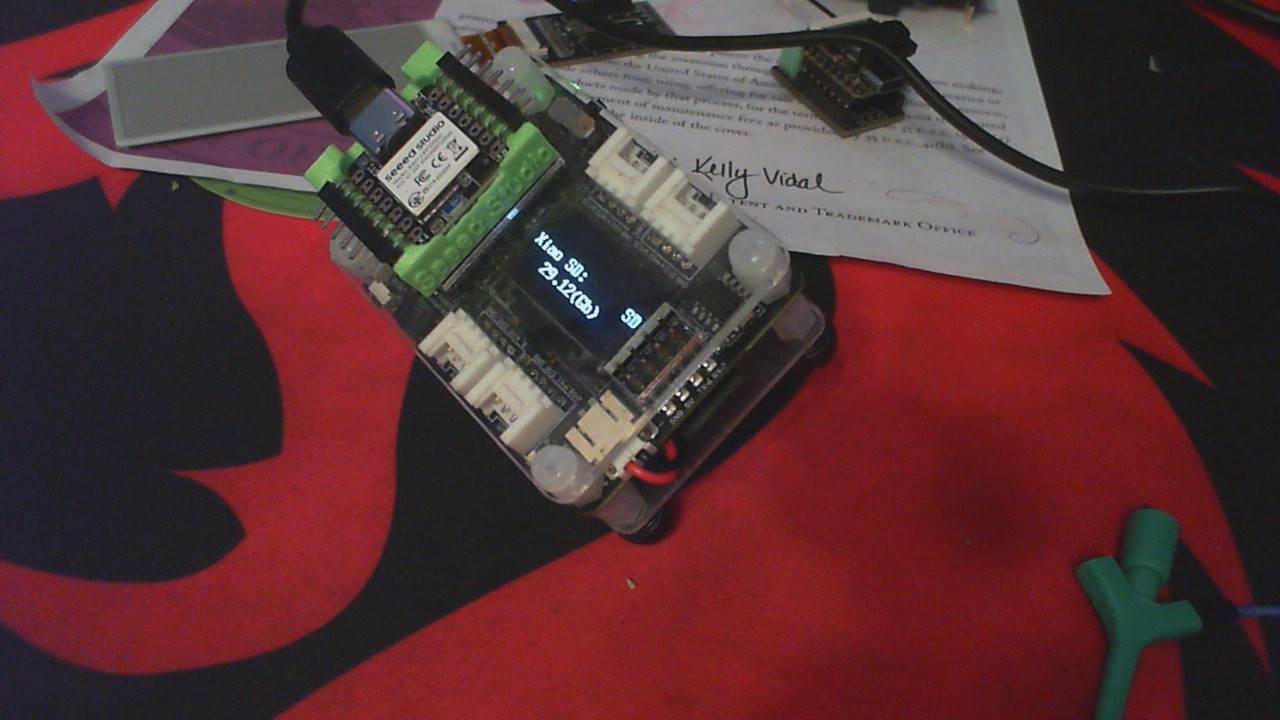
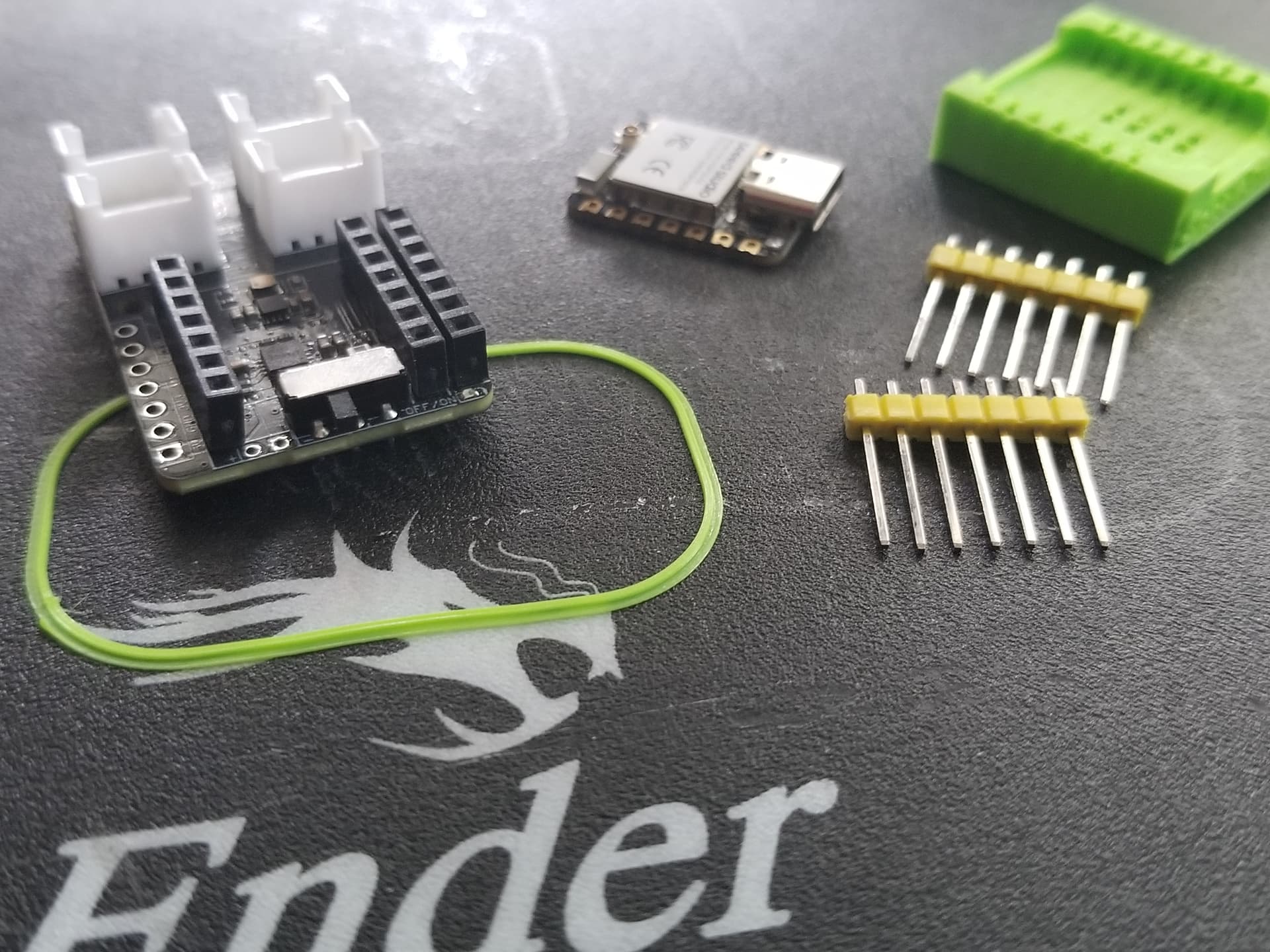
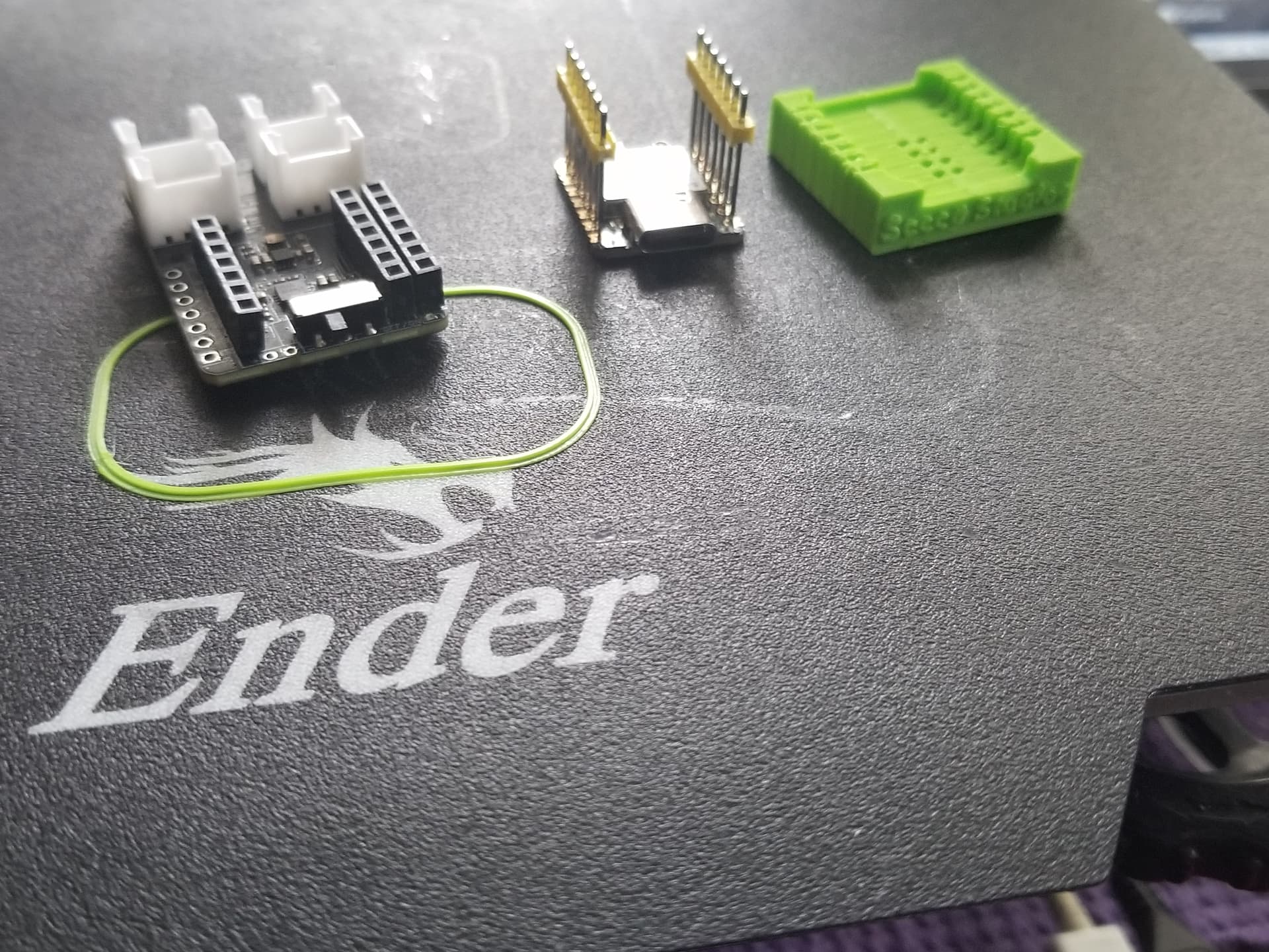
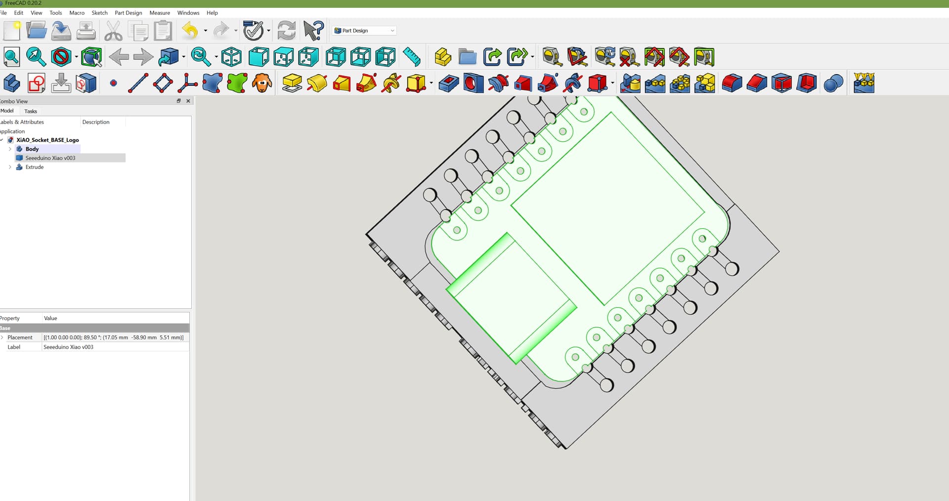
SO , I (we) now have a newer improved version of the original, Xiao 3D printed socket. It is Skinnier so it fits better, includes another set of pin holes (makes it footprint compatible) the older version required you to add another female pin row as seen in the pictures, This New one is Nrf, C3,S3 and C6 Xiao compatible, and I did have to move the POGO pin position up slightly *" thanks @KrrK " *so it’s why it’s marked as a WIP . ![]()
I’ll add in a PCB to slip in underneath with Pogo’s and a 8 pin small pitch dual row connector SWD compatible ( UART) debug. soon.
You can add your own also.
Pins are all you need and it Supports Stacking, If you know how. check it out.
I rarely solder them anymore ![]() Files are included in the Zip here, and I’ll add 'em to thingiverse (b4 some rips-off posts on Etsy) shortly
Files are included in the Zip here, and I’ll add 'em to thingiverse (b4 some rips-off posts on Etsy) shortly ![]()
these sockets are all inspired by “Renzo” he did the first ESP32 one it was giant but worked well and as a Tech we begged for stuff like that.
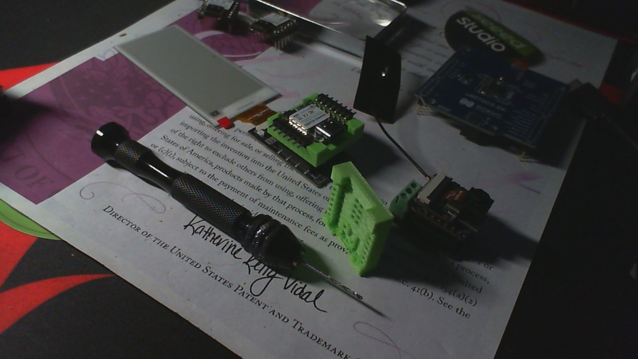
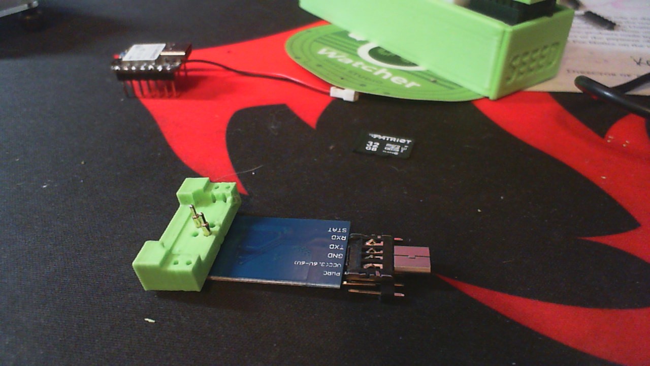
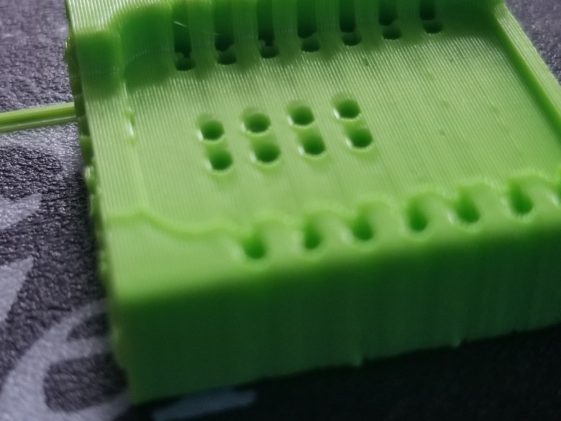
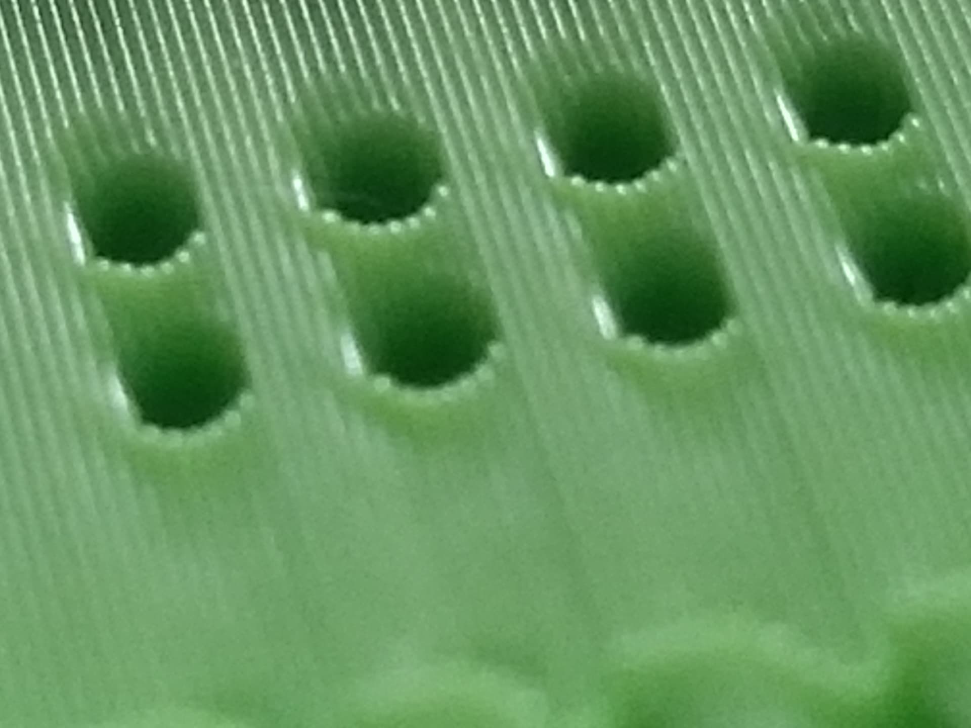
You made your own pins from old Axial resistor cutoff’s, they were just malleable enough but still held the shape. These more rigid pins I use makes the tech more like a “Shark-Bite” connection (for all the plumbers and mygyvers out there) ![]() You see first pic it bites into the Pin and there is a Pin in the Hole also, the push against each other makes it a solid connection no Soldering
You see first pic it bites into the Pin and there is a Pin in the Hole also, the push against each other makes it a solid connection no Soldering
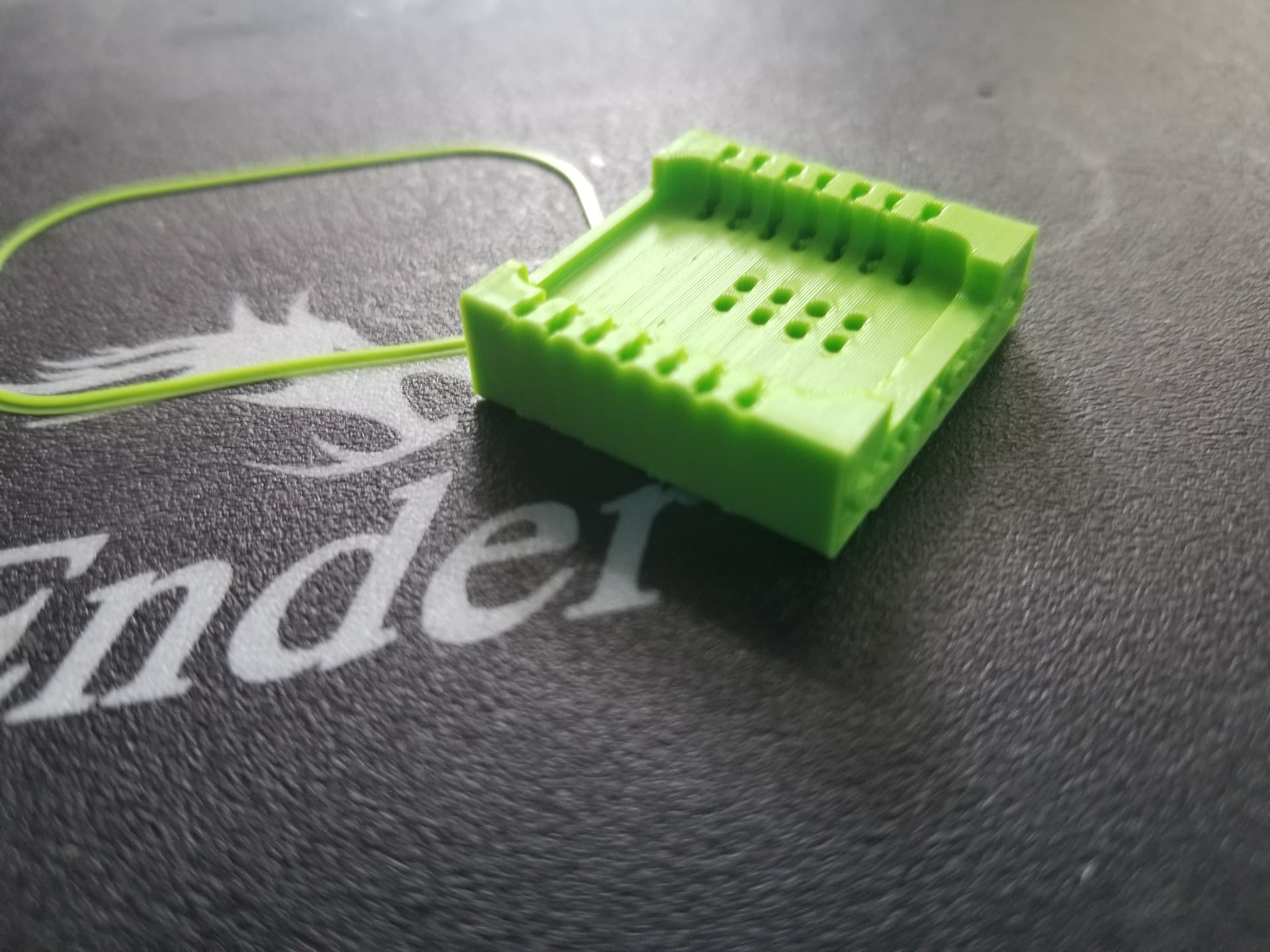
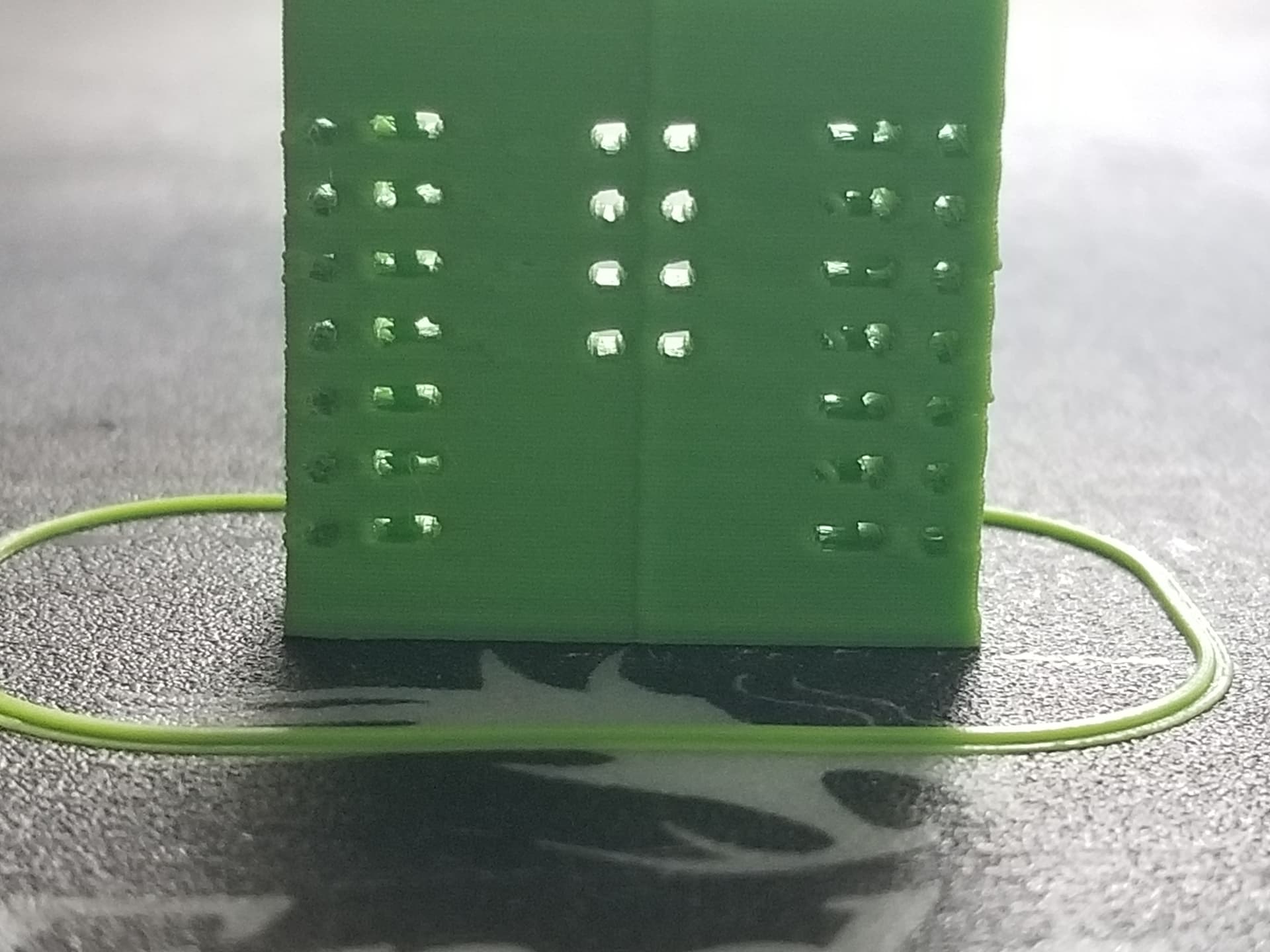
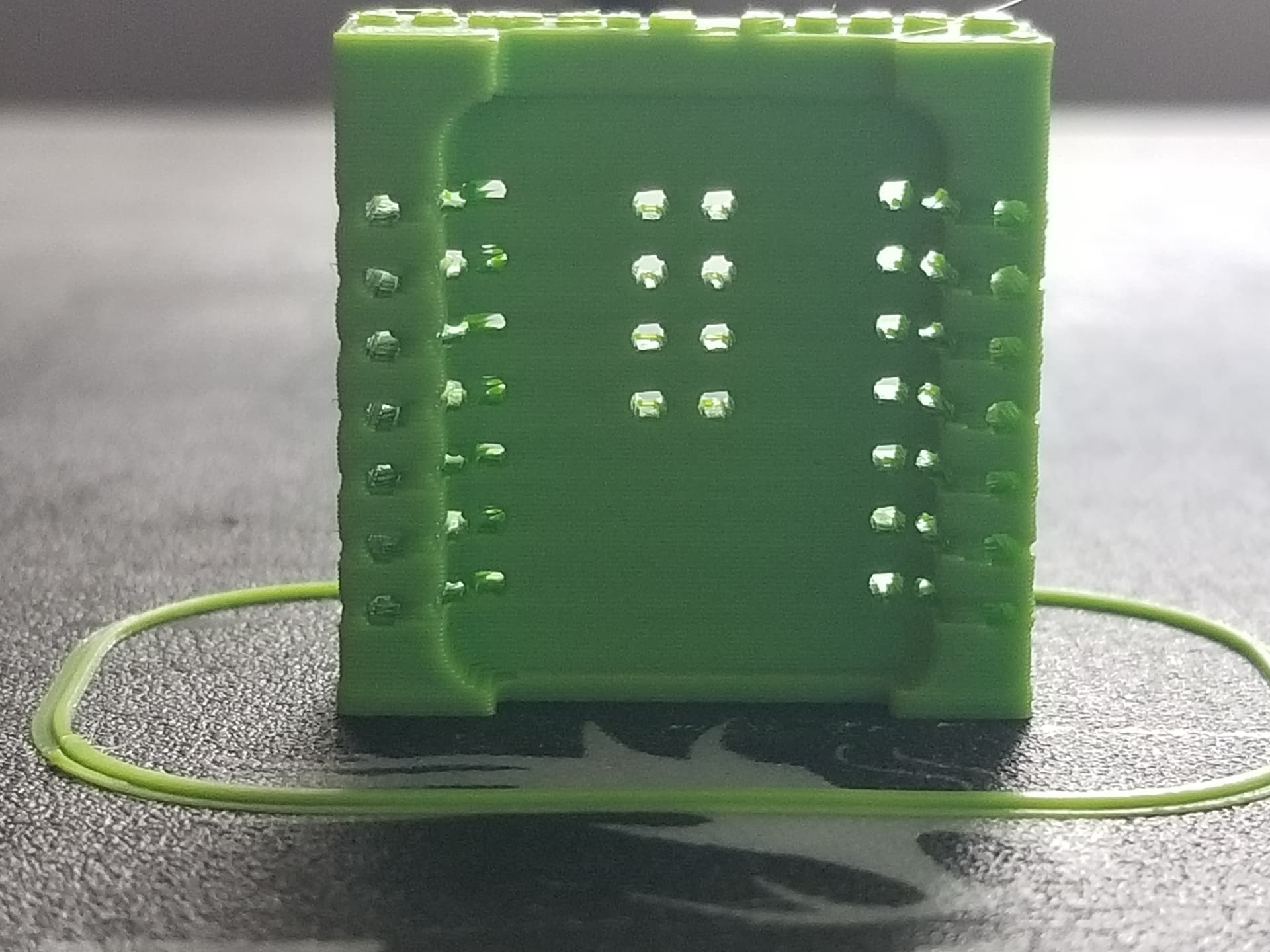
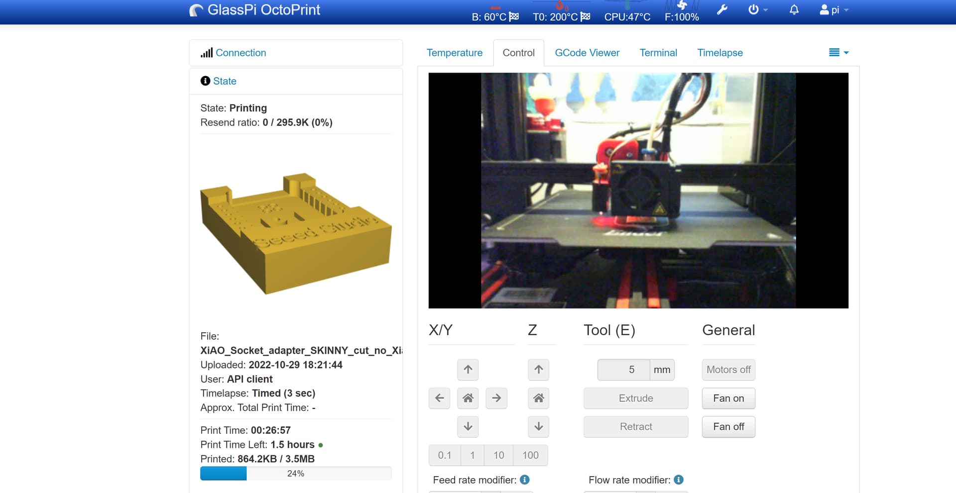
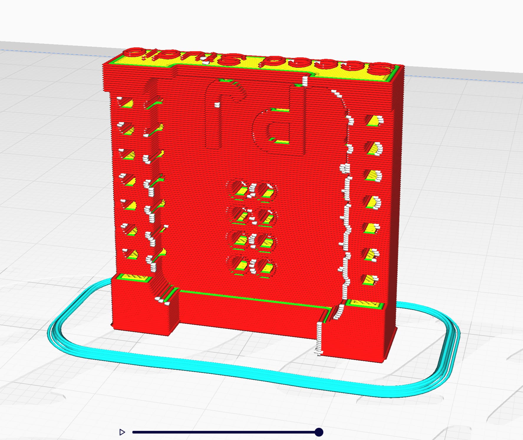
It is printed and pictured here in that sweet Seeed Green PLA+ at 50% , HB 65, nozzle 205, dry, dry filament, sunlu. no supports , prints standing AOK.
Pins are from digi-key or Amazon?
You can even use it as a spacer , the through Hole pre-Soldered Xiao will mount up …
HyperLapse, print one today! ![]()

GL ![]() PJ
PJ ![]()
XiAO_Socket_Post.zip (2.6 MB)