Hi, Anyone used I2C on Xiao MG24? The same simple sketch worked on XIAO NRF version but unfortunately failed on MG24. Are there any known bugs in XIAO MG? I am using Arduino platform.
Hi there,
So Check this thread, there were some early issues but AFAIK it’s all sorted now.
HTH
GL ![]() PJ
PJ ![]()
For boards like the XIAO MG24 Sense, the onboard IMU might require enabling a specific GPIO pin (e.g., PD05) to power the sensor. Additionally, using the FlexWire library instead of the standard Wire library has been effective in some cases.
Most of examples uses Xiao in I2C master mode. I use it an I2C slave and it simply does not work. The same code and setup for NRF works.
Submit your sketches.
I have both the nRF52 and MG24 on hand so I can try them out.
Master code running on ESP32:
    Serial.println("Initializing I2C...");
    Wire.begin(I2C_SDA, I2C_SCL);
    Wire.setClock(400000); // Set I2C clock speed to 100kHz
    //delay(3000);  // Give time to boot
    Serial.println("Scanning I2C bus...");

    for (uint8_t addr = 1; addr < 127; addr++) {
        Wire.beginTransmission(addr);
        if (Wire.endTransmission() == 0) {
            Serial.print("Found device at 0x");
            Serial.println(addr, HEX);
        }
        delay(100);
        }

    delay(2000);
    Serial.println("I2C scan complete.");
MG24 code running as slave:
setup(){
...
  Wire.begin(0x42);
...
Scanner reports I2C device on all addresses. Maybe I have faulty module… The same code on NRF works.
The master is ESP32, correct? Have you ever run it on a non-ESP32 board? For example ESP32C3_XIAO.
Please post the entire sketchs.
How many ohms is the pull-up resistors?
Master is ESP 32 S3 board (not Xiao), 4.7k pullup resistors.
Slave MG24 code:
#include <Wire.h>

#define I2C_ADDRESS 0x42

uint8_t buffer[12];  // Dummy 12-byte data

void onRequestHandler() {
  Wire.write(buffer, sizeof(buffer));
  Serial.println("buffer sent");
}

void setup() {
  Serial.begin(115200);
  delay(100);

  // Fill buffer with dummy data for testing
  for (int i = 0; i < sizeof(buffer); i++) {
    buffer[i] = i + 1;
  }

  Wire.begin(I2C_ADDRESS);  // Start as I2C slave
  Wire.onRequest(onRequestHandler);

  Serial.println("MG24 I2C Slave ready");
}

void loop() {
  delay(100);
}
Master Code:
#include <Arduino.h>
#include <Wire.h>

void setup() {
  Serial.begin(115200);
  delay(1000);
  Serial.println("Starting I2C scan on GPIO16 (SDA) and GPIO21 (SCL)");
  Wire.begin(16, 21);
}

void loop() {
  byte error, address;
  int nDevices = 0;

  Serial.println("Scanning...");

  for (address = 1; address < 127; address++) {
    Wire.beginTransmission(address);
    error = Wire.endTransmission();

    if (error == 0) {
      Serial.print("I2C device found at 0x");
      Serial.println(address, HEX);
      nDevices++;
    }
    delay(50); // Small delay to allow for I2C bus to stabilize
  }

  if (nDevices == 0) {
    Serial.println("No I2C devices found.");
  }

  delay(5000);
}
The result of scanning:
I2C device found at 0x1
I2C device found at 0x2
I2C device found at 0x3
… (all addresses)
I2C device found at 0x7D
I2C device found at 0x7E
I have tried with the MG24 and nRF52 using the ESP32S3_XIAO as the master.
No problem with nRF52, but MG24 does not detect 0x42 as you say.
When I connect the SCL of MG24, the SCL of S3 goes LOW and I2C stops working. The cause is under investigation.
EDIT:
The MG24 is returning ACK to all calls from the master. nRF52 is only returning ACK to calls to 0x42.
With MG24 as a Leader (aka master) try this…
  for (address = 1; address < 127; address++) {
    Wire.beginTransmission(address);
    Wire.write(0xFF); //Send 1 dummy byte
    i2c_error = Wire.endTransmission();

    if (i2c_error == 0) {
      Serial.print("I2C device found at 0x");
      Serial.println(address, HEX);
      nDevices++;
    }
Neither SCL nor SDA will change.
Do you know why NACK is not output except 0x42?
At this stage the only suggestion I have requires modifying Wire.cpp to include an I2C_SlaveAddressMaskSet command.
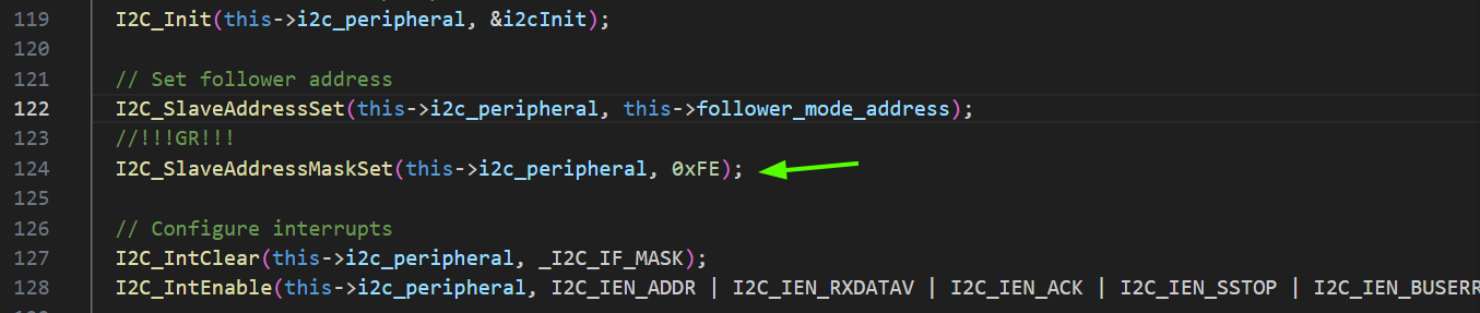
There may be (or should be) a function to do this from the setup.
It won’t return ACK even for 0x42!
I wonder if the cause of the problem in this thread is that the MG24 I2C slave is not designed to respond to I2C_scanner.
Sorry to hear that.
It works for me here but I’m using MG24<->MG24 at the moment. I could try with a C6, C3 or S3 or RP2350 later.
Here’s my “follower” code…
#define SLAVE_ADDRESS 0x42

void setup() {
  Wire.begin(SLAVE_ADDRESS << 1);  // Join I2C bus as a slave with address 0x42
  Wire.onReceive(receiveEvent);    // Register event handler for receiving data
  Wire.onRequest(requestEvent);    // Register event handler for sending data
  Serial.begin(115200);
  while (!Serial)
    ;  // Wait for the serial port to connect
  Serial.println("I2C Slave Device Ready");
}
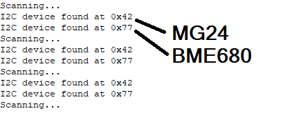
Edit> I have tested with ESP32-S3 and it scans fine. Same as in picture above.
Could you post a complete sketch of the S3 and MG24? I will check the waveforms.
This is the S3 scan code.
#include <Arduino.h>
#include <Wire.h>

#define LED_ON 0  // Active Low
#define LED_OFF 1

void setup() {
  pinMode(LED_BUILTIN, OUTPUT);
  Serial.begin(115200);
  while (!Serial) {
    digitalWrite(LED_BUILTIN, !digitalRead(LED_BUILTIN));
    delay(100);
  }

  digitalWrite(LED_BUILTIN, LED_ON);
  Serial.println("Initializing I2C...");
  Wire.begin();

  Serial.println("I2C Scanner Starting...");
}

void loop() {
  uint8_t i2c_error, address;
  int nDevices = 0;

  Serial.println("Scanning...");

  for (address = 1; address < 127; address++) {
    Wire.beginTransmission(address);
    i2c_error = Wire.endTransmission();

    if (i2c_error == 0) {
      Serial.print("I2C device found at 0x");
      Serial.println(address, HEX);
      nDevices++;
    }
    digitalWrite(LED_BUILTIN, !digitalRead(LED_BUILTIN));
    delay(50);  // Small delay to allow for I2C bus to stabilize
  }

  if (nDevices == 0) {
    Serial.println("No I2C devices found.");
    digitalWrite(LED_BUILTIN, LED_OFF);
  } else {

    digitalWrite(LED_BUILTIN, LED_ON);
  }

  delay(5000);
}
The code for the slave is the same as above apart from line 21 where I use the following
Wire.begin(I2C_ADDRESS << 1); // Start as I2C slave
So…
#include <Wire.h>

#define I2C_ADDRESS 0x42

uint8_t buffer[12];  // Dummy 12-byte data

void onRequestHandler() {
  Wire.write(buffer, sizeof(buffer));
  Serial.println("buffer sent");
}

void setup() {
  Serial.begin(115200);
  delay(100);

  // Fill buffer with dummy data for testing
  for (int i = 0; i < sizeof(buffer); i++) {
    buffer[i] = i + 1;
  }

  Wire.begin(I2C_ADDRESS << 1);  // Start as I2C slave
  Wire.onRequest(onRequestHandler);

  Serial.println("MG24 I2C Slave ready");
}

void loop() {
  delay(100);
}
0x42 << 1 = 0x84, but scanner will only scan up to 0x7F. “>>1” is removed, the MG24 will return ACK at all addresses.
I have tried the sketches you posted, but the situation does not improve. There must be some difference with your environment.
I have an SSD1306 connected to the I2C bus instead of a pull-up resistor.
Did you modify your Wire.cpp?
I tried reinstalling BSP 2.3.0, but the situation remains the same.
MG24 returns ACK at all addresses. nRF52 returns ACK only at 0x42(7bit) 0x84(8bit).
I have 2.3.0 installed and modified the Wire.cpp as mentioned above.
I try not to think too much ![]() but I think that the Wire.begin for the follower case is not quite correct.
but I think that the Wire.begin for the follower case is not quite correct.
The follower (slave) address should be the I2C address shifted left by 1, viz 0x84 as the LSB is the R/W bit.
Essentially in Wire.cpp, line 79, there should be
this->follower_mode_address = follower_mode_address << 1;
Then the shift doesn’t need to be in the (ino) code…
2 Likes