The Arduino IDE does not have an OV2640.c file.
You would need to solder a (fine) wire onto pin 8 of the camera connector on the sense board. Not easy.
The Arduino IDE does not have an OV2640.c file.
You would need to solder a (fine) wire onto pin 8 of the camera connector on the sense board. Not easy.
You don’t need to modify OV2640.c. Just call the sensor->set_reg_bits(… ) function directly.
Regarding PWDN I had ruled out altering the existing Sense board. I thought if PJ_Glasso were to reverse engineer it in Eagle CAD (like his More I/O board) he could connect Camera pin 8 (PWDN) to, say, IO21/USER_LED.
‘sensor_t’ {aka ‘struct _sensor’} has no member named ‘set_reg_bits’; did you mean ‘set_reg’?
21 is also used as SD CS.
Sorry - I meant:
int ret = set_reg_bits(sensor, BANK_SENSOR, COM2, 4, 1, enable?1:0);
In the Seeed expansion board schematic there is a D2/SD_CS coming in from the CPU and this is grouped up with D8/D9/D10 and labelled as “SD Card” however D2 is connected through R11 which is marked as DNP (Do not place) so D2, despite the labelling doesn’t actually control the SD CS. As you point out the SD card CS pin is in fact driven by IO21/USER_LED through R12. Given that all the example code says use pin 21 I guess it would be perverse to change it despite the schematic labelling. So, PWDN could instead be controlled by D2/SD_CS on a re-engineered Sense board.given that it is not used for anything else. Basically, there is a spare GPIO going through that connector and it could be used to drive the hardware PWDN pin of an OV2640.
Does not seem to exist in the Arduino IDE core 2.0.14 for ESP32.
Were you using the Arduino IDE ?
For a PWDN pin you could grab one of the MIC pins …
Ah yes. Looking at my notes I see I could not access set_reg_bits either however set_reg is accessible. I called it as sensor->set_reg(sensor, 0x109, 0x10, 0x10) but I got:
E (61522) sccb: SCCB_Write Failed addr:0x30, reg:0x09, data:0x12, ret:263
just as the other guy reported. This seems to imply that the camera does shutdown but the SCCB interface closes too and cannot complete the write properly.
NB 0x109 does the bank switch and addresses register 09 all in one go
with all this sleep current talk… im gonna def have to take a nap…
![]()
One of the issues does appear to be differences between the library that espressif publish on the Github and whats included in the Arduino IDE.
For instance there is no ov2640.c file in the Arduino IDE, most of the code used seems hidden inside pre complied files so you dont seem to be able to see the exact form of functions such as set_reg() etc…
I think what has been compiled into the Arduino platform for esp32 is the full published driver code however the external api is what is published as esp-camera.h and sensor.h in driver/include. So you can’t see functions declared in the files in sensors/private_include, which is where set_reg_bits is found.
When you include the driver files in your sketch I think you are allowing your code to reference compiled functions in .a files that are part of the platform. You can probably download the esp-camera library from github, rename and modify it and then reference your own alternative library instead of the one in the platform. That would allow you to add extra functionality or correct mistakes in the library. I haven’t tried this yet but if the author of the library doesn’t respond to some of my issues I may try this.
When you call set_reg() you are not calling the Ov2640.c implementation directly. You are calling the set_reg() function stored in the sensor_t structure. When you initialise the camera a pointer to the Ov2640 implementation of it gets stored there. So you are limited in what you can call in the sensor specific .c files to what pointers have been copied into the sensor_t structure. But you are ultimately running the published code in Ov2640.c. Or ov3660.c as appropriate
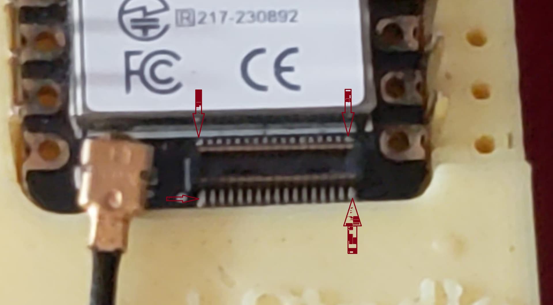
A sandwich board is a really good idea in principle (and I’m going to salt that idea away for future reference) however in this case the PWDN pin (pin 8) on the 24-pin ‘golden finger’ camera connector is pulled down to GND by R10 (10k) on the Sense expansion board so no amount of switching pins in the B2B connector is going to fix that.
Hi, despite all my efforts and trying all proposed solutions, it seems that the camera is still powered quite a lot when put in sleep. After to only 10 minutes of “supposed” sleep, it was heating significantly ![]()
I think I’m going for the solution of an external Pro Mini driving a MOSFET. The Pro Mini has a 5uA deep sleep current so it is hard to beat.
Hi there,
So , do give a good visual inspection. Look for any solder bridges or cold joints. Try the Heatsink also but we feel your pain it’s NOT optimum for sure. Seeed would do well to Rework this unit an make a number of improvement. IMO
GL ![]() PJ
PJ ![]()