Seeed Studio Forum
Xiao esp32s3 sense camera sleep current
Products & Technology
XIAO
PJ_Glasso
September 4, 2024, 12:21am
56
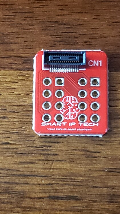
More I/O
5b6f8e9d4a80a9984197f46d5c14a37c12ef402d_2_420x750
420×750 92.5 KB
1 Like
show post in topic