I purchased a XIAO-ESP32-S3 with an expansion shield Grove-Shield-for-Seeeduino-XIAO-embedded-battery-management-chip and a ST7789 1.22" diplay (Grove 1.2-inch IPS Display | Seeed Studio Wiki)
1st problem:
The wiki entry from the display speaks of SPI, but in the image it shows I2C naming.
I don’t understand, like at all.
The datasheet is also extremely hard to understand, as it talks about the strangest interfaces.
What interface is used? As far as I can see there is only code for SPI displays for ST7789.
2nd problem:
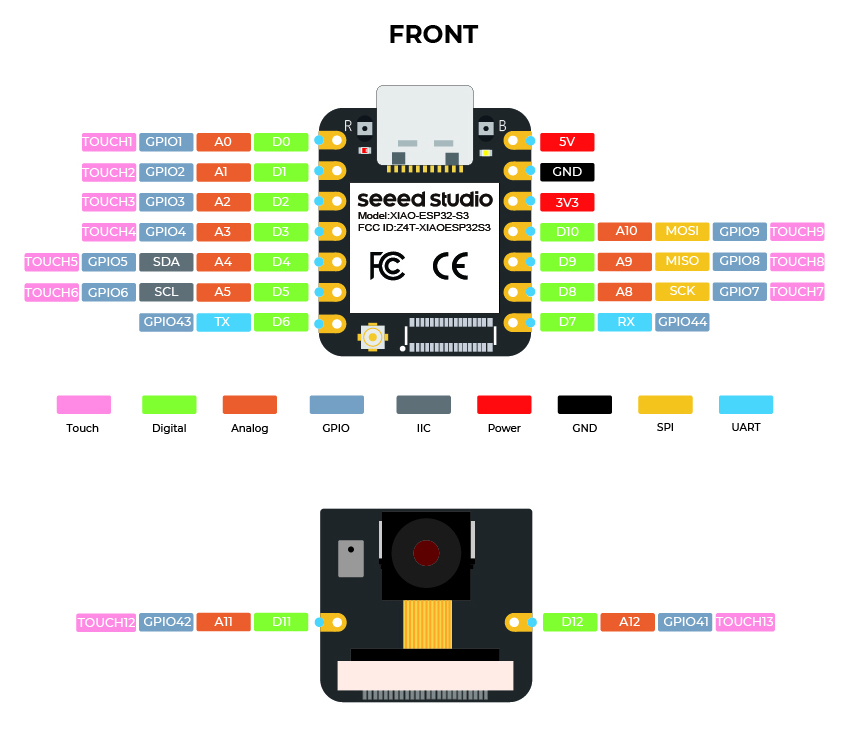
As far as I understand (I only found SPI code only for ST7789) I need to connect MOSI from ESP32 to DTA display and SCK to SCK.
The is no connector on the expansion board that has D10 (MOSI) and D8 (SCK) on it for it to fit the provided seeedstudio connector.
See: files.seeedstudio.com/wiki/Grove-Shield-for-Seeeduino-XIAO/img/pinout.png
SPI Pins for the display:
MOSI (DTA) → “SDA” label on the display
SCK (Clock) → “SCL” label on the display
You will also need:
CS (Chip Select): Usually tied to a GPIO pin
DC (Data/Command): Another GPIO pin
RST (Reset): Optional but usually required for initialization
Yeah, that’s how I am used to it.
The problem is that a) there are no CS DC or RST pins available with this display board and b) the connector and the breakout board are not pin compatible with the display, so although they use the same molex seeedstudio connectors I cannot plug them together…
Guess have to cut and solder the display to the XIAO pinheader making the breakout board useless.
So yea, it is a Feature not a bug, also known as I2C in this case
Simplified Interface: The display adopts a serial SPI interface and only requires the SCK and SDA connections to the main controller. This greatly simplifies user operation and saves time on wiring.
There is plenty of example code here for this exact unit. use the search and you will find it I have one on here with the similar display, connected to the Expansion board.
No, use the Wire lib and the I2c pins.
All pins are available on expansion board BTW.
I am having a similar problem. I have a XIAO ESP32S3, I thought it was SPI pins but I saw from this thread that it is I2C pins. I have SCK(The yellow wire) on the lcd display board connected to D5 on the ESP32S3 and we have DATA(The white wire) on pin D4.
The software that I am using I have taken from the grove 1.2inch display https:://wiki.seeedstudio.com/grove_1.2inch_ips_display/. And we have verified that the XIAO is working because the arduino blink example is working. When we run the example from the 1.2inch lcd display page after downloading the libraries, it does not come with the Adafruit GFX Library. We have counteracted that by installing the Adafruit GFX library and the Adafruit-BusIO library for the Adafruit gfx libraries compatibility requirements. After doing this we get this error:
In file included from C:\Users\\Documents\Arduino\libraries\Arduino_ST7789_Fast-master\Arduino_ST7789_Fast.cpp:5:
C:\Users\\Documents\Arduino\libraries\Arduino_ST7789_Fast-master\Arduino_ST7789_Fast.cpp: In member function 'void Arduino_ST7789::sckHigh()':
C:\Users\\Documents\Arduino\libraries\Arduino_ST7789_Fast-master\Arduino_ST7789_Fast.h:23:27: error: 'PORTD' was not declared in this scope
   23 | #define    LCD_SCK_SET    PORTD |= (1 << PORTD7);           // SET SCK HIGH
which happens when we run the ST7789 Hello World example as suggested by the grove lcd 1.22 docs
SO it’s not a tool at all, It’s the Board Support Package You choose it from the boards Tab in Arduino 2.x Some of the older LIB require older BSP’s so Roll it back from what you have if it’s the current version 3.1.1
Sorry for the delayed reply, I had become very busy during that time. I am using Arduino 2.3.4. My BSP is version 3.0.0(3.0.1 didn’t work :/). And I still get the same error. Do I need to roll back further or what library should I use in alternative for the xiao 1.22" display?
I’m sorry PJ, we tried 3.0.7 but it was to no avail. Our 1.22" LCD is I2C and only has two connection pins clock and data compared to the 4 that the usual one has. Is there anything we can do to get it to work?
SO post up the code you are trying to use, S3 correct So with it’s SPI and IC2 you need to define the pins explicitly with the interfaces selected “begin” Post upp the compiler output, First 3 lines and the last 12 -15 lines b4 the Upload. I can look.
Also have a look at the link in this thread , compare the output you get with the ones in that thread above. If you have an UNO also would be worth trying(learning) the difference
I’m using the examples included in the library, which I’ve already used with an ESP32 Dev 1 and it works correctly, but I’m unable to get it working with the Xiao ESP32 S3 Plus.
I’m using Arduino IDE 2.3.6 and I’ve selected the Xiao ESP32 Plus. I believe the pinout is correct because it works correctly for analog readings and digital inputs and outputs.
Hello, I’m still having trouble getting my Xiaomi S3 Plus to work with the ST7789 screen.
So I decided to use an ESP32 S3 Dev to see if it would work. With this pin configuration, it worked correctly: #define TFT_MISO 13 #define TFT_MOSI 11 #define TFT_SCLK 12 #define TFT_CS -1 // Chip select control pin #define TFT_DC 6 // Data Command control pin #define TFT_RST 7 // Reset pin (could connect to RST pin)
Of course, I enabled the HSPI port with #define USE_HSPI_PORT
So the problem isn’t with the screen. I’m back to using the S3 Plus. I tried using these pin configurations: #define TFT_MISO 12 #define TFT_MOSI 11 #define TFT_SCLK 13 #define TFT_CS -1 // Chip select control pin #define TFT_DC 6 // Data Command control pin #define TFT_RST 5 // Reset pin (could connect to RST pin)
Without any results.
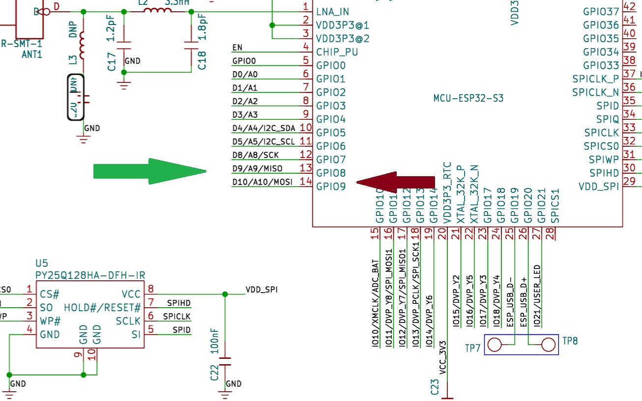
What I’ve seen is that on the ESP32 S3 Dev, pin 13 is MISO and pin 12 is SCLK, while the S3 Plus pinout indicates 13 as SCLK and 12 as MISO.
I understand that since it’s the same microcontroller, the pins should be the same. This is puzzling.
But I’ve tried both configurations and neither works. I still don’t understand what’s going on.
So , those are different but the same…
Can you post the code You are trying to Run us e the code tags above “</>” past it in there,
Your code should use the GPIO numbers not pin (silkscreen) numbers.
also the TFT_eSPI.sys is BSP sensitive, works best with specific ones.