GM,
OK I did it by your instructions.
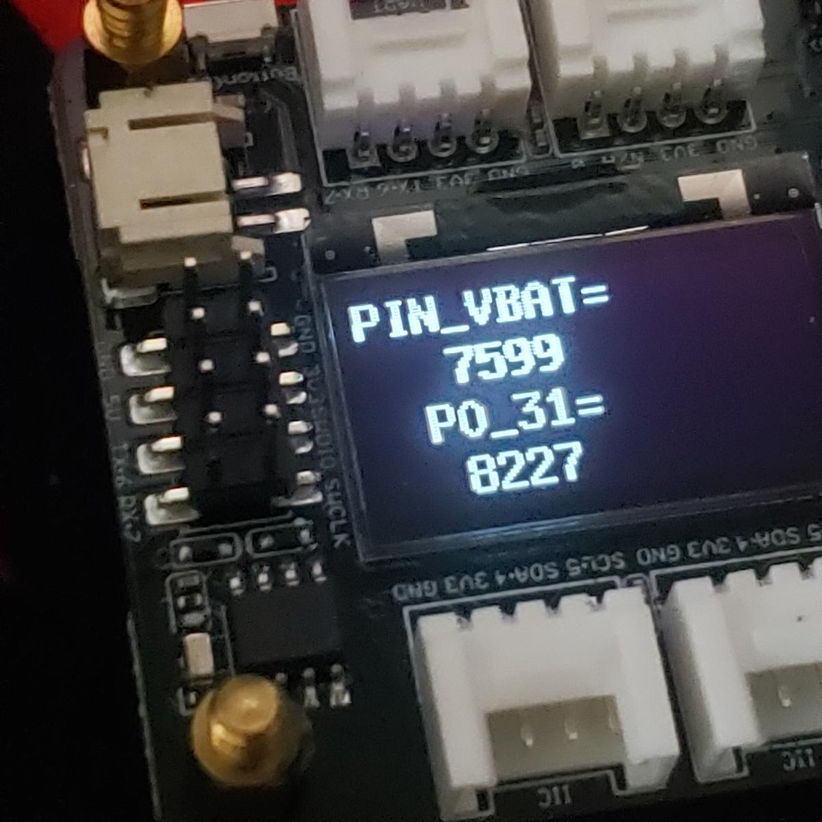
Appears to work but the numbers are different?
HTH
GL ![]()

code + Chop
//----------------------------------------------------------------------------------------------
//CHOP CHOP
//Board Library : Seeed nRF52 mbed-enable Borads 2.9.1
//Board Select  : Seeed nRF52 mbed-enable Borads / Seeed XIAO BLE - (nRF52840)
//2023/02/12
//Arduino15\packages\Seeeduino\hardware\mbed\2.9.1\variants\SEEED_XIAO_NRF52840/
//  replase pins_arduino.h and variant.cpp
//----------------------------------------------------------------------------------------------
#include <Arduino.h>
#include <U8x8lib.h>
//#define LED LED_BUILTIN         // default
//#define LED LEDR
#define LED LEDG
//#define LED LEDB
//#define LED P0_26   // RED
//#define LED P0_30   // GREEN
//#define LED P0_6    // BLUE
//Create a instance of class
U8X8_SSD1306_128X64_NONAME_HW_I2C u8x8(/* clock=*/PIN_WIRE_SCL, /* data=*/PIN_WIRE_SDA, /* reset=*/U8X8_PIN_NONE);  // OLEDs without Reset of the Display

const int analogInPin = PIN_VBAT;
bool state = false;


void setup() {
  Serial.begin(9600);
  while (!Serial);
  delay(3000);//relax...Get Ready for serial port
  Serial.println();
  Serial.println("Power ON \n ");  // Let's BEGIN!!
  Serial.println("Test program compiled on " __DATE__ " at " __TIME__);
  Serial.println();
  Serial.println("Processor came out of reset.");
  u8x8.begin();
  u8x8.setFlipMode(1);  // set number from 1 to 3, the screen word will rotary 180
  u8x8.setFont(u8x8_font_8x13B_1x2_r);
  u8x8.clearDisplay();
  u8x8.setCursor(0, 0);
  u8x8.print("Power ON ");
  delay(3000);

  pinMode(PIN_VBAT_ENABLE, OUTPUT);   // P0_14
  digitalWrite(PIN_VBAT_ENABLE, LOW);
  pinMode(PIN_CHARGE_HIGH, OUTPUT);   // P0_13
  digitalWrite(PIN_CHARGE_HIGH, LOW);
}

void loop() {
  state = !state;
  digitalWrite(LED, (state ? LOW: HIGH));
  digitalWrite(LED, state);
  u8x8.clearDisplay();
  u8x8.setCursor(0, 0);
  u8x8.print("PIN_VBAT=");
  u8x8.setCursor(3, 2);
  u8x8.print((analogRead(PIN_VBAT) * 3 * 3300) / 1024);
  digitalWrite(LED_GREEN, LOW);
  u8x8.setCursor(0, 4);
  u8x8.print("  P0_31=");
  u8x8.setCursor(3, 6);
  u8x8.print((analogRead(P0_31) * 3 * 3300) / 1024);

  Serial.print("PIN_VBAT=");
  Serial.print((analogRead(PIN_VBAT) * 3 * 3300) / 1024);
  Serial.print(" P0_31=");
  Serial.print((analogRead(P0_31) * 3 * 3300) / 1024);
  Serial.println();

  delay(500);
  setupblink();

}

//========================functions===============

void initdisplay() {
  pinMode(LEDR, OUTPUT);  // initialize the LED pin as an output:
  pinMode(LEDG, OUTPUT);  // initialize the LED pin as an output:
  pinMode(LEDB, OUTPUT);
  pinMode(LED_BUILTIN, OUTPUT);  // initialize the LED pin as an output:
  u8x8.begin();
  u8x8.setFlipMode(1);  // set number from 1 to 3, the screen word will rotary 180
  u8x8.setFont(u8x8_font_8x13B_1x2_r);
  u8x8.clearDisplay();
  u8x8.setCursor(0, 0);
  u8x8.print("Power ON ");
}
void setupblink() {

  setLedRGB(false, true, false);  // Red
  delay(1000);
  setLedRGB(true, false, false);  // Green
  delay(1000);
  setLedRGB(false, false, true);  // Blue
  delay(1000);
  setLedRGB(false, false, false);  // OFF
}

void setLedRGB(bool red, bool green, bool blue) {

  if (!blue) {
    digitalWrite(LEDB, HIGH);
  } else {
    digitalWrite(LEDB, LOW);
  }
  if (!green) {
    digitalWrite(LEDG, HIGH);
  } else {
    digitalWrite(LEDG, LOW);
  }
  if (!red) {
    digitalWrite(LEDR, HIGH);
  } else {
    digitalWrite(LEDR, LOW);
  }
}
Output
Power ON

Test program compiled on Feb 14 2023 at 11:59:31

Processor came out of reset.
PIN_VBAT=8343 P0_31=8459
PIN_VBAT=8382 P0_31=8478
PIN_VBAT=8343 P0_31=8527
PIN_VBAT=8353 P0_31=8517
PIN_VBAT=8343 P0_31=8488
PIN_VBAT=8333 P0_31=8459