I’m starting to think tha we all would benefit if we create a github repo with a schematic of the bare xiao ble sense with a simple demostration of making this board to deep sleep AND recover via some pulse/Button.
Some simple schematic with two buttons. Sleep AND wake. Something with a basic arduino IDE project and a platform.io alternative. I’m very basic at electronics, but I managed to get the basic xiao samd to sleep and recover in just 2 hours. And i’ve spent days trying to figure out this one (without success) which is crazy…
If no one does this I will create a public repo in a few days with some of my failures and some basic stuff we could use to learn how to deep sleep this xiao
The Bluefruit is a library built to work with the Nordic softdevice. If you want to use BLE then you have three choices. Write your own register level code. Use the Mbed version of the XIAO BLE Sense library for BLE or use the Adafruit (version 1) of the XIAO BLE Sense library, which is Bluefruit.
Many people seem to have problems with the Mbed libraries and use the Adafruit instead because they are much better documented.
In most cases, the Mbed library, and the Adafruit library are not compatible. You have to make a choice.
Hi thanks for replying!, which code do you think is valid for bare XIAO BLE SENSE (no groove, just plain xiao) with Adafruit bootloader?
I’ve tested many of the added codes but some of them include specific interrupts for groove or just makes the xiao to go shutdown and restart constantly.
As soon as I manage to get this one working I’ll share a github with just an example of this. I’m still find quite difficult to follow some conclusions of this thread, including some others like @Noblauch that seem still having issues.
Hi, Seems like apples and oranges, I’m using successfully the “double tap” for interrupt generation and the accelerometer config to generate it. and for the shut down or sleep, the most important is the delay after
nrf_gpio_cfg_sense_input(digitalPinToInterrupt(int1Pin), NRF_GPIO_PIN_PULLDOWN, NRF_GPIO_PIN_SENSE_HIGH);
delay(2000); // delay seems important to apply settings, before going to System OFF
  NRF_POWER->SYSTEMOFF = 1;
otherwise the system wakes back up immediately.
My demo with code will stay asleep for as long as I don’t touch(Tap) it. 2-3 days easy.
HTH
GL :-p
Seeed has two versions of the board files (not the hardware).
uses the Mbed structure/libraries
uses Adafruit libraries and bootloader and the Nordic softdevice.
Mbed has their own BLE library and Adafruit has its own BLE library.
The ArduinoBLE library that is used with the Arduino Nano BLE 33 board is also used with the XIA BLE board that was setup for Mbed.
The Adaftuit BLE library is called with Bluefruit.begin() and is used with the XIAO BLE that is using the Adafruit setup… Programs written for the Mbed setup of the XIAO BLE most of the time do not work with XIAO BLE board using the Adafruit setup.
So when you install your XIA BLE board in the Arduino IDE, you need to decide which board files (and libraries) you want to use: Mbed or Adafruit.
We also failing to get into the deep sleep, would be nice get some improvement soon. otherwise it will be quite hard to use XIAO BLE sense for wearable projects.
hi,
I tried to run your code with my xiao ble nrf52840 sense and it indeed going to sleep after 5 double tabs BUT it doesn’t wake up on the 6. I tried everything and it just staying in deep sleep!
I am new to the iot world, maybe I am doing something wrong
here what i did:
#include "LSM6DS3.h"
#include "Wire.h"
LSM6DS3 myIMU(I2C_MODE, 0x6A); // IMU
#define int1Pin PIN_LSM6DS3TR_C_INT1

const int ledPin = LED_BUILTIN; // set ledPin to on-board LED

uint8_t interruptCount = 0; // Amount of received interrupts
uint8_t prevInterruptCount = 0; // Interrupt Counter from last loop

void setup() {
  Serial.begin(9600);
  while ( !Serial ) delay(10);   // for nrf52840 with native usb
  pinMode(ledPin, OUTPUT); // use the LED as an output

  Serial.println("Hello, I am awake!");
  myIMU.settings.gyroEnabled = 0; // Gyro currently not used, disabled to save power
  if (myIMU.begin() != 0) {
    Serial.println("IMU error");
  } else {
    Serial.println("IMU OK!");
  }

  setupDoubleTapInterrupt();

  pinMode(int1Pin, INPUT);
  attachInterrupt(digitalPinToInterrupt(int1Pin), int1ISR, RISING);
}

void loop() {
  setLED(false);
  Serial.print("Interrupt Counter: ");
  Serial.println(interruptCount);

  if (interruptCount > prevInterruptCount) {
    Serial.println("Interrupt received!");
  }
  prevInterruptCount = interruptCount;

  if (interruptCount >= 5) {
    // Trigger System OFF after 5 interrupts
    goToPowerOff();
  }

  delay(500);
}

void goToPowerOff() {
  Serial.println("Going to System OFF");
  setLED(true);
  setupDoubleTapInterrupt();
  delay(1000); // delay seems important to apply settings, before going to System OFF
  //Ensure interrupt pin from IMU is set to wake up device
  nrf_gpio_cfg_sense_input(digitalPinToInterrupt(int1Pin), NRF_GPIO_PIN_PULLDOWN, NRF_GPIO_PIN_SENSE_HIGH);
  // Trigger System OFF
  NRF_POWER->SYSTEMOFF = 1;
}

void setupDoubleTapInterrupt() {
  uint8_t error = 0;
  uint8_t dataToWrite = 0;

  // Double Tap Config
  myIMU.writeRegister(LSM6DS3_ACC_GYRO_CTRL1_XL, 0x60); //* Acc = 416Hz (High-Performance mode)// Turn on the accelerometer
  // ODR_XL = 416 Hz, FS_XL = 2g
  myIMU.writeRegister(LSM6DS3_ACC_GYRO_TAP_CFG1, 0x8E);// INTERRUPTS_ENABLE, SLOPE_FDS// Enable interrupts and tap detection on X, Y, Z-axis
  myIMU.writeRegister(LSM6DS3_ACC_GYRO_TAP_THS_6D, 0x85);// Set tap threshold 8C
  myIMU.writeRegister(LSM6DS3_ACC_GYRO_INT_DUR2, 0x7F);// Set Duration, Quiet and Shock time windows 7F
  myIMU.writeRegister(LSM6DS3_ACC_GYRO_WAKE_UP_THS, 0x80);// Single & double-tap enabled (SINGLE_DOUBLE_TAP = 1)
  myIMU.writeRegister(LSM6DS3_ACC_GYRO_MD1_CFG, 0x08);// Double-tap interrupt driven to INT1 pin
}

void int1ISR() {
  interruptCount++;
}

  void setLED(bool on)
  {
  // data = 1 -> LED = On
  // data = 0 -> LED = Off
  digitalWrite(LED_BUILTIN, on ? HIGH : LOW);
  }
So this was bugging me as to why it worked and for other it doesn’t
I reran a cut and paste of your original code posted and ONLY added the delay;
didn’t work here either so, I got my original code and it DIDN’T work either. WTH?
Went back , loaded 2.9.0
Using board 'xiaonRF52840' from platform in folder: C:\Users\Dude\AppData\Local\Arduino15\packages\Seeeduino\hardware\mbed\2.9.0
Using core 'arduino' from platform in folder: C:\Users\Dude\AppData\Local\Arduino15\packages\Seeeduino\hardware\mbed\2.9.0
Good news YOUR code worked with delay to put to sleep and to wakeup AOK.
HTH
GL
#include "LSM6DS3.h"
#include "Wire.h"
LSM6DS3 myIMU(I2C_MODE, 0x6A); // IMU
#define int1Pin PIN_LSM6DS3TR_C_INT1

const int ledPin = LED_BUILTIN; // set ledPin to on-board LED

uint8_t interruptCount = 0; // Amount of received interrupts
uint8_t prevInterruptCount = 0; // Interrupt Counter from last loop

void setup() {
  Serial.begin(9600);
  while ( !Serial ) delay(10);   // for nrf52840 with native usb
  pinMode(ledPin, OUTPUT); // use the LED as an output

  Serial.println("Hello, I am awake!");
  myIMU.settings.gyroEnabled = 0; // Gyro currently not used, disabled to save power
  if (myIMU.begin() != 0) {
    Serial.println("IMU error");
  } else {
    Serial.println("IMU OK!");
  }

  setupDoubleTapInterrupt();

  pinMode(int1Pin, INPUT);
  attachInterrupt(digitalPinToInterrupt(int1Pin), int1ISR, RISING);
}

void loop() {
  setLED(false);
  Serial.print("Interrupt Counter: ");
  Serial.println(interruptCount);

  if (interruptCount > prevInterruptCount) {
    Serial.println("Interrupt received!");
  }
  prevInterruptCount = interruptCount;

  if (interruptCount >= 5) {
    // Trigger System OFF after 5 interrupts
    goToPowerOff();
  }

  delay(500);
}

void goToPowerOff() {
  Serial.println("Going to System OFF");
  setLED(true);
  setupDoubleTapInterrupt();
  delay(1000); // delay seems important to apply settings, before going to System OFF
  //Ensure interrupt pin from IMU is set to wake up device
  nrf_gpio_cfg_sense_input(digitalPinToInterrupt(int1Pin), NRF_GPIO_PIN_PULLDOWN, NRF_GPIO_PIN_SENSE_HIGH);
  delay(2000);// Trigger System OFF
  NRF_POWER->SYSTEMOFF = 1;
}

void setupDoubleTapInterrupt() {
  uint8_t error = 0;
  uint8_t dataToWrite = 0;

  // Double Tap Config
  myIMU.writeRegister(LSM6DS3_ACC_GYRO_CTRL1_XL, 0x60); //* Acc = 416Hz (High-Performance mode)// Turn on the accelerometer
  // ODR_XL = 416 Hz, FS_XL = 2g
  myIMU.writeRegister(LSM6DS3_ACC_GYRO_TAP_CFG1, 0x8E);// INTERRUPTS_ENABLE, SLOPE_FDS// Enable interrupts and tap detection on X, Y, Z-axis
  myIMU.writeRegister(LSM6DS3_ACC_GYRO_TAP_THS_6D, 0x85);// Set tap threshold 8C
  myIMU.writeRegister(LSM6DS3_ACC_GYRO_INT_DUR2, 0x7F);// Set Duration, Quiet and Shock time windows 7F
  myIMU.writeRegister(LSM6DS3_ACC_GYRO_WAKE_UP_THS, 0x80);// Single & double-tap enabled (SINGLE_DOUBLE_TAP = 1)
  myIMU.writeRegister(LSM6DS3_ACC_GYRO_MD1_CFG, 0x08);// Double-tap interrupt driven to INT1 pin
}

void int1ISR() {
  interruptCount++;
}

  void setLED(bool on)
  {
  // data = 1 -> LED = On
  // data = 0 -> LED = Off
  digitalWrite(LED_BUILTIN, on ? HIGH : LOW);
  }
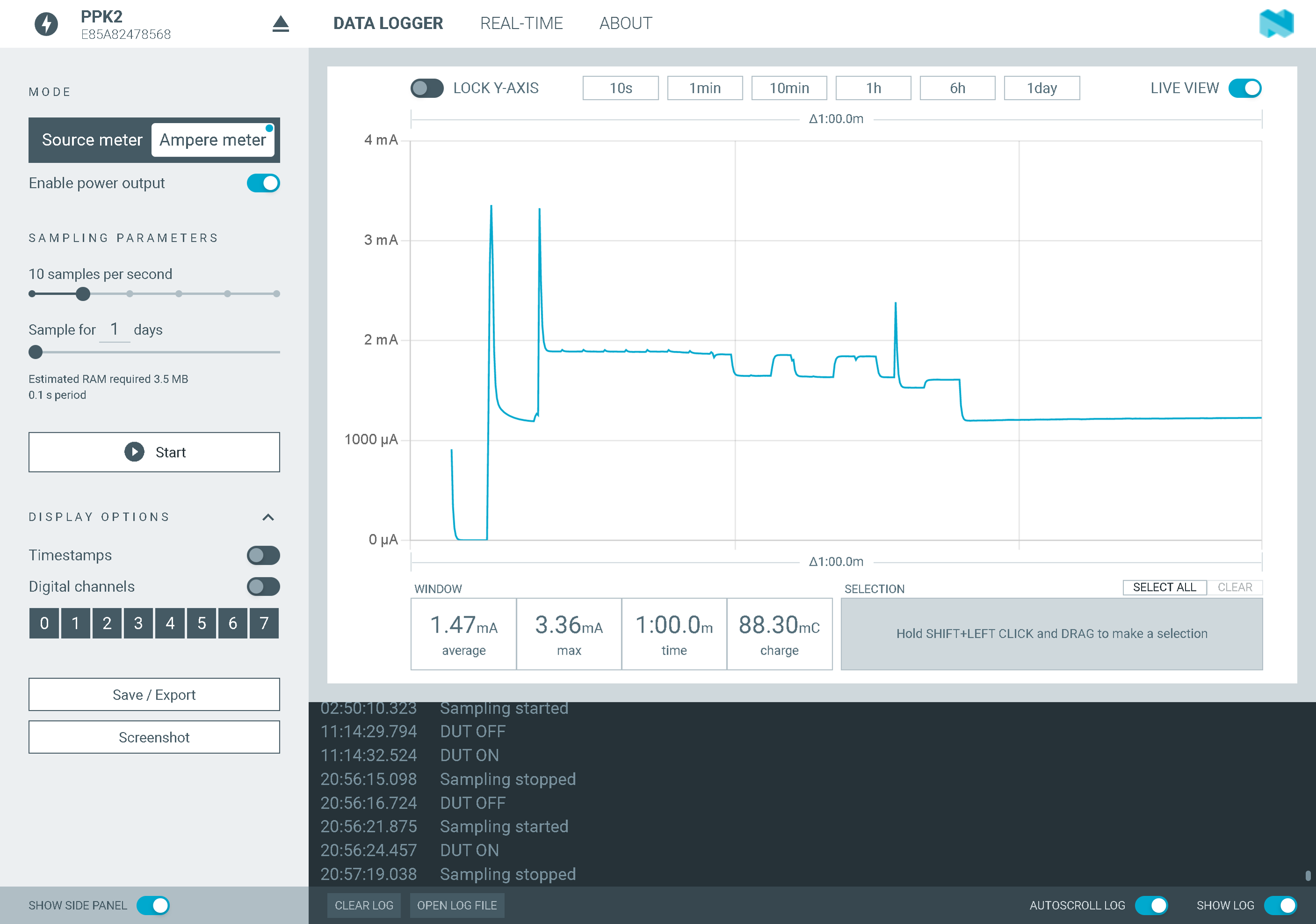
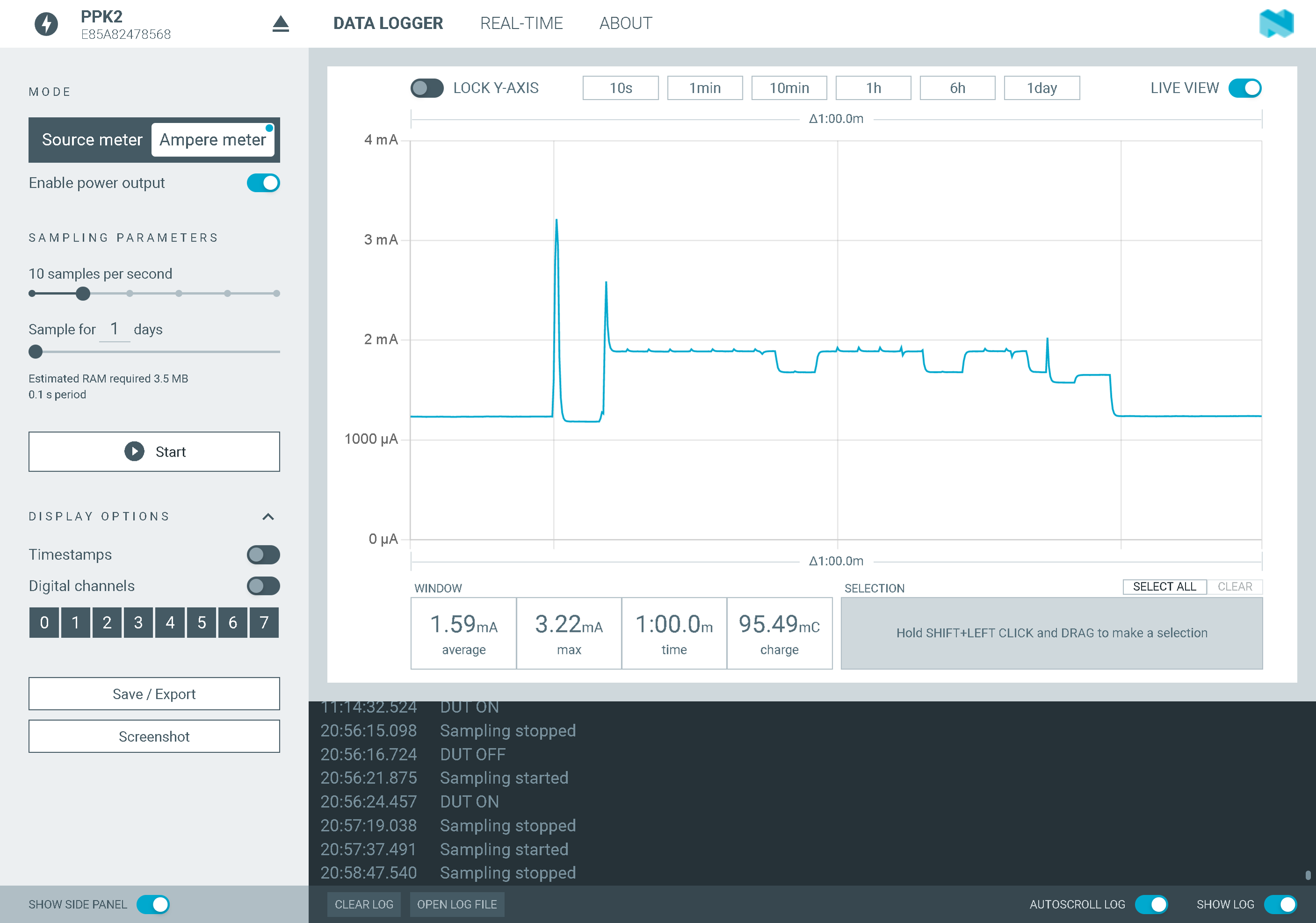
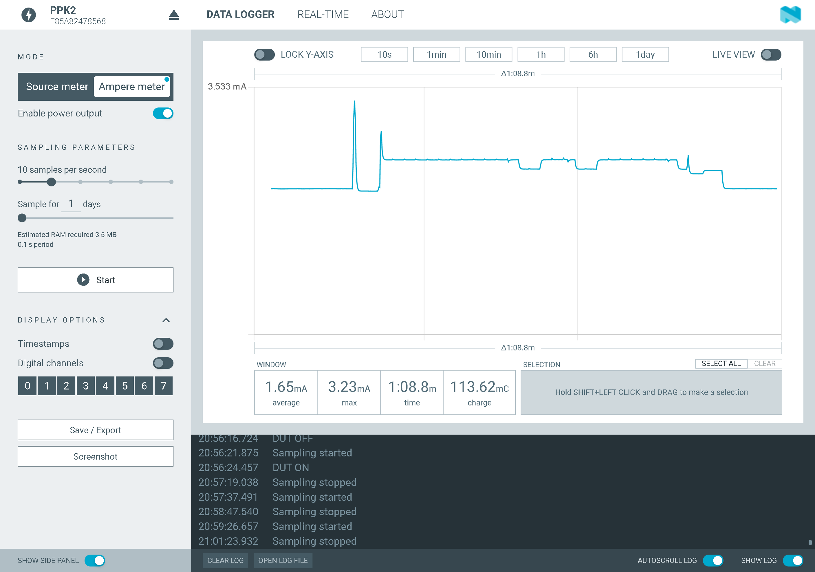
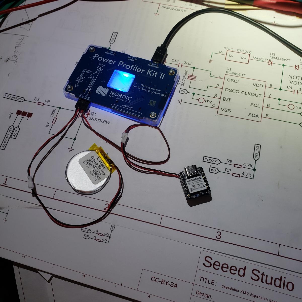
Highly recommend the $Hondo… My code on my prototype has gone from 6hrs , as-is on an 450 Mah 3.85 Vdc battery with some adjustments went to 11 hrs, I was happy …Now 72 hrs. with allot more to go…
@Citric@fe7565@PJ_Glasso a lot of a good info about mbed vs adafruit board firmwares and sleep mode.
I was able to find examples how to do timer-based interrupts for mbed firmware, but not for the Adafruit/Bluefruit one. Do you know if timer-based interrupts are supported/working on non-mbed firmware?
Also, is it possible to use timer-based interrupts to wake device using either mbed or Bluefruit firmware?
so if I want to “power down” the XIAO and all connected peripherals and wake it up again with a button, is this possible or not? What’s the lowest current that can be achieved like this?
I have once done this with an Adafruit nrf52840 board and got a battery usage when powered down way less than its self-discharge
So actually no one, not even Seeed, knows how to power this thing down and up again just like basically every portable eletronic device nowadays is powered up / down, meaning with the push (long press?) of a button?
Is this really true?