Hi there,
LOL ![]() A picture of the DUT , setup ? Can’t be anything proprietary , is it in an enclosure.?
A picture of the DUT , setup ? Can’t be anything proprietary , is it in an enclosure.?
can you post the code ?
GL ![]() PJ
PJ ![]()
Hi there,
LOL ![]() A picture of the DUT , setup ? Can’t be anything proprietary , is it in an enclosure.?
A picture of the DUT , setup ? Can’t be anything proprietary , is it in an enclosure.?
can you post the code ?
GL ![]() PJ
PJ ![]()
I would imagine that “since the default state of RF_SW is on the transmit side, it works fine in transmit mode, however it does not switch to receive mode when receiving, so it appears to be less sensitive.”
If the shield is open and pins 4 and 6 can be observed, it would make sense to check if the logic is inverted during transmit and receive.
Checking with the simplest possible setup and firmware may help to identify the problem!
As above, pin 4 and 6 has been observed and confirmed to be correct. These modules are permanently either in Tx or Rx mode. It does not toggle. And our code has been checked, reviewed and scanned thru, and that only initialization part drives the GPIOA-PA4/5 into the respective state once.
Are you at least saying that you observed that the state of pins 4 and 6 are different in the Tx and Rx modules?
Is there any possibility that the radio library could manipulate pins 4 and 6 after setting them by GPIO?
No, we scan thru every code possible, and live-view the GPIOA register. It did not change.
Latest…I have just confirmed, that the chip does not work well in SF6. Switching to SF7 normalised these reading (RSSI and SNR). However, range is still very bad. At 80dB path loss, it start to show very bad lost packets
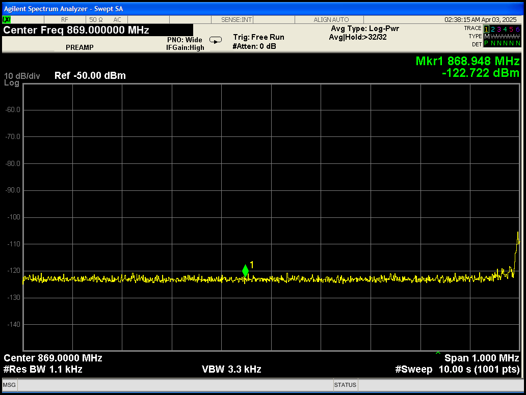
Received RSSI, is reading -68dBm to -75dBm. But SNR reads -7 to -9dB. On my Spectrum Analyzer, the channel is clean. Something is not right, and we have got no clue.
jFYI again, this is Seeed Lora-E5, running a STM32WL5 inside.
Hi there,
So No Picture? No Code? Your “RF_expert” is out of Ideas?
You try another set of units,
Have you considered another Model then? Others have tested " Theses "
and NO-one has reported and problems, SO I would re-review your settings and timings. Check any solder work or modifications. I would also switch to antennas and try some additional testing. But your information is confusing, without seeing what it is you say is the problem.
GL ![]() PJ
PJ ![]()
@PJ_Glasso You should be able to switch between TX and RF much faster than at 100 ms intervals. The time for echoes to die down in a given RF link is microseconds, not hundreds of milliseconds. Your code in the Wio-SX1262 thread has “leakage” from TX to RX because you use radio.transmit() instead of radio.startTransmit(). Just like with reception, transmission end is signaled as an interrupt on DIO1, which will trigger your receive function. Since SX1262 uses a shared transmit/receive buffer, when you go to read the buffer after this interrupt you end up reading the data you just transmitted as a result. Jgromes recommends using the dual-interrupt approach used in the Radiolib SX1262 Ping Pong example to avoid this. I had issues with TX/RX leakage and after switching to using filtered interrupts for both TX and RX, I have not had this happen once since.
Hi there,
Yes, You are correct Sir… LOL ![]() I saw that and was able to get it much Faster, I have same demo code using interrupt ,Just DOI1 is all you get though. This was just some quick code to show the New Hardware works, None had been posted prior, only Meshtangle
I saw that and was able to get it much Faster, I have same demo code using interrupt ,Just DOI1 is all you get though. This was just some quick code to show the New Hardware works, None had been posted prior, only Meshtangle ![]() existed on the wiki early on. It’s slowly coming out.
existed on the wiki early on. It’s slowly coming out.
I’ll be testing more with different ant and add the GPS, Stay tuned I’m sure We are just scratching the surface on it. ![]() Great stuff though forsure
Great stuff though forsure ![]()
GL ![]() PJ
PJ ![]()
I added a comment to Jgromes Git to add it ![]()
This change is all that’s needed: Ping?pong example…
// uncomment the following only on one
// of the nodes to initiate the pings
#define INITIATING_NODE                     // don't forget this on ONE end of the Pair for testing!

// SX1262 has the following connections:
// NSS pin:   10
// DIO1 pin:  2
// NRST pin:  3
// BUSY pin:  9
// SX1262 radio = new Module(10, 2, 3, 9);
SX1262 radio = new Module(41, 39, 42, 40); //support for the Wio_SX-1262 & Xiao ESP32S3 with B2B connector.
// or detect the pinout automatically using RadioBoards
// https://github.com/radiolib-org/RadioBoards
/*
just an fyi, if anyone wants to run his git tools ![]()
PJ,
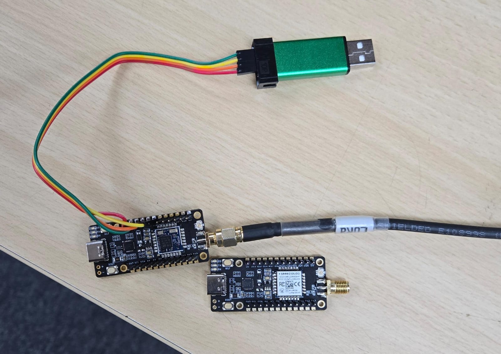
I may not understand exactly what are you looking for. If you want picture, let me add some. I cannot share the exact code, but the main library is direct official from ST-microelectronics. This is verified over a few units, very repeatable. why switch antenna, when VNA shows better than -15dB RL?
The setup is simple enough, that I do not understand what is to share. We are still prototyping off Seeed Lora E5 Mini…as cited.
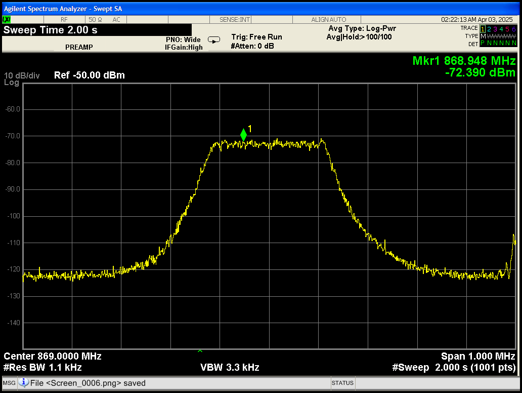
The main test now, as shown on a spectrum analyzer, is 20m, across 4 walls. Showing very strong CNR (or SNR), and yet the Lora module reads -8dB SNR at times, with a RSSI of -68dBm to -75dBm. The SA’s noise floor is also shown, showing no other in-band signal. Even at -80dBm, there is no reason for SNR of -8dB
As shown in the link below, I am already communicating over 20 km using the same device as shown in your photo. If you are having problems with the same device, it is not a hardware issue.
We need more information on the exact information to get closer to your problem.
“Programming LoRa-E5 with Arduino, LoRa-E5 mini Point to Point Comminucation over 24 km”
We are indeed, trying to figure out, what else in the config/library can go wrong. Everything on paper, on instruments, show that everything is in order. We can get ZERO packet loss when its another 6dB stronger, and then hell break loss even when we are still long way from the noise floor. We are doing a 19byte packet, and is doing it at 40millisecond per packet, in case someone knows something wrong here.
We already sure, the RSSI reading in SF6 does NOT work, so definately strange, if errata did not state anything.
One thing in question, how’s your test area’s noise in term of cellular signal. A
We do have cellular here at 760MHz, and 885MHz onwards. am wondering if that is the cause.
We have nothing in front of us to verify what you are saying is normal. Each post contains numbers that indicate the situation, but they are vague and we don’t understand them well. Maybe if you could sort out what the problem is and provide information, not the situation, so that people viewing the post can understand it, it might solve the problem.
Hi there,
So maybe just the setup of the code would help us? Help You ![]()
Here a simple observation, I had a couple wacky setup issues that disappeared after I set the Baud Rate to 9600 from the 115200 is was defaulted to. I don’t know if a certain config gets corrupted or sent with a frame error or WHAT? Try that just for grins, slow your init down it may be dropping some params.
I’m doing this to cycle through the modes and testing.,
// REV 6.0b - Mode 1 Beacon Sender
// Project: Mode it to the Max
// Board: ESP32-S3 with SX1262 LoRa Module
Initializing SX1262 LoRa radio... SUCCESS!

LoRa Mode Table:
Mode | SF | BW (kHz) | CR
-----|----|----------|----
  1  |  7 |   125.0  | 4/5
  2  |  8 |   125.0  | 4/5
  3  |  9 |   125.0  | 4/5
  4  | 10 |   125.0  | 4/5
  5  | 11 |   125.0  | 4/5
  6  | 12 |   125.0  | 4/5
  7  | 10 |    62.5  | 4/5
  8  | 11 |    62.5  | 4/5
  9  | 12 |    62.5  | 4/5
 10  | 12 |    31.25 | 4/8

Using Mode 1 Parameters:
  Spreading Factor: SF7
  Bandwidth: 125.0 kHz
  Coding Rate: 4/5
  TX Power: 22 dBm
Transmitting every 5 seconds...

Sent: Seeed Studio
Sent: Seeed Studio
Sent: Seeed Studio
Sent: Seeed Studio
Sent: Seeed Studio
Sent: Seeed Studio
Sent: Seeed Studio
Sent: Seeed Studio
I think you may need to STOP. ![]()
Take a break and try again with the regular pair and test them first with canned code and, then go again with your code ![]()
Send some real data… see what you get. I didn’t see anything in your comments of you setting up a baseline test and what you were trying to achieve , Good thing is there are a lot of folks on here that can help overcome pretty much anything!
HTH
GL ![]() PJ
PJ ![]()
Keep going and pushing forward , You’ll get there I hear some hound dog in there so stay at it. ![]()
@paulwu - Your transmission rate is quite fast. Is the 40mS the space between packets or the rate at which each packet is sent?
What are your settings?
SF - 7
Freq - 915Mhz?
BWidth - 25khz?
CR - 4/5?
Preamble - 12 (fixed)
Airtime for a 19 byte packet with same settings as above is about 52mS. If sending every 40mS there may be an issue.
Paulwu
I have several LoRa-e5 mini and a simple spectrum analyzer on hand. If you are experimenting with just the LoRa-E5 mini, I can reproduce it here with your hex files.
I apologise if was at first misleading. We intend to eventually use the module, but now prototyping with the Mini to get us started first.
We used the original library from ST, and do not know what minimal firmware to go at.
When we moved to SF7, testing is done at 70ms. 40ms was for SF6.
My setting is
SF 6/7
CR 4/5
BW 250kHz
Freq 865 to 869
19byte payload
With crc n implicit header.
I get perfect comm up to 300m. Antenna is handtuned, reception via SA shows good output, including at the receive side.
When RSSI drop to about -70dBm, SNR starts to drop to negative region randomly, and start to loss packet.