@salman, actually I don’t have the white jumper wires in the Grove interface cables. So for RX, I’ve fitted two white jumper wires separately (for the two Radio modules).
That’s fine, I meant is, check you jumper cable is working or not! you can use a multimeter or something to get the continuity.
Just now I checked them… For faults…
No errors, working excellently.
From the starting, I think there is something wrong with the code, because the code I am using is for working using a UART interface. Whereas, I don’t have a UART interface. I think, there should be few changes in the code, according to how I’m doing.
Kindly help me regarding that… Or your opinion?You can take a look at my sketch.
Kindly say something… As directed by you, I checked my jumper wires for faults but they’re working finely.
You have one, The RX and TX is part of the UART Interface! Can you share the code you are working?
Yeah, I’ve the pins which are available on all Arduino Uno boards (TX & RX). But I’m taking about a single-board UART Shield (Like the Seeeduino Lotus and Grove Base Shield V2.0 for Arduino), because in the tutorial the Seeeduino Lotus has been used.
I’ve used the same code, as given in the Seeed Studio wiki of LoRa Radio (https://wiki.seeedstudio.com/Grove_LoRa_Radio/).
These are the codes of the Radio Transmitter and Receiver:
RF95_Client (Code)
// rf95_client.pde
// -*- mode: C++ -*-
// Example sketch showing how to create a simple messageing client
// with the RH_RF95 class. RH_RF95 class does not provide for addressing or
// reliability, so you should only use RH_RF95 if you do not need the higher
// level messaging abilities.
// It is designed to work with the other example rf95_server
// Tested with Anarduino MiniWirelessLoRa

#include <SoftwareSerial.h>
#include <RH_RF95.h>


// Singleton instance of the radio driver
SoftwareSerial ss(5, 6);
RH_RF95 rf95(ss);


void setup()
{
    Serial.begin(115200);
    Serial.println("RF95 client test.");

    if (!rf95.init())
    {
        Serial.println("init failed");
        while(1);
    }

    // Defaults after init are 434.0MHz, 13dBm, Bw = 125 kHz, Cr = 4/5, Sf = 128chips/symbol, CRC on

    // The default transmitter power is 13dBm, using PA_BOOST.
    // If you are using RFM95/96/97/98 modules which uses the PA_BOOST transmitter pin, then
    // you can set transmitter powers from 5 to 23 dBm:
    //rf95.setTxPower(13, false);

    rf95.setFrequency(434.0);
}

void loop()
{
    Serial.println("Sending to rf95_server");
    // Send a message to rf95_server
    uint8_t data[] = "Hello World!";
    rf95.send(data, sizeof(data));

    rf95.waitPacketSent();

    // Now wait for a reply
    uint8_t buf[RH_RF95_MAX_MESSAGE_LEN];
    uint8_t len = sizeof(buf);

    if(rf95.waitAvailableTimeout(3000))
    {
        // Should be a reply message for us now
        if(rf95.recv(buf, &len))
        {
            Serial.print("got reply: ");
            Serial.println((char*)buf);
        }
        else
        {
            Serial.println("recv failed");
        }
    }
    else
    {
        Serial.println("No reply, is rf95_server running?");
    }

    delay(1000);
}
RF95_Server (Code)
// rf95_server.pde
// -*- mode: C++ -*-
// Example sketch showing how to create a simple messageing server
// with the RH_RF95 class. RH_RF95 class does not provide for addressing or
// reliability, so you should only use RH_RF95  if you do not need the higher
// level messaging abilities.
// It is designed to work with the other example rf95_client
// Tested with Anarduino MiniWirelessLoRa


#include <SoftwareSerial.h>
#include <RH_RF95.h>


// Singleton instance of the radio driver
SoftwareSerial ss(5, 6);
RH_RF95 rf95(ss);

int led = 13;


void setup()
{
    Serial.begin(115200);
    Serial.println("RF95 server test.");

    pinMode(led, OUTPUT);

    if(!rf95.init())
    {
        Serial.println("init failed");
        while(1);
    }
    // Defaults after init are 434.0MHz, 13dBm, Bw = 125 kHz, Cr = 4/5, Sf = 128chips/symbol, CRC on

    // The default transmitter power is 13dBm, using PA_BOOST.
    // If you are using RFM95/96/97/98 modules which uses the PA_BOOST transmitter pin, then
    // you can set transmitter powers from 5 to 23 dBm:
    //rf95.setTxPower(13, false);

    rf95.setFrequency(434.0);
}

void loop()
{
  if(rf95.available())
  {
    // Should be a message for us now
    uint8_t buf[RH_RF95_MAX_MESSAGE_LEN];
    uint8_t len = sizeof(buf);
    if(rf95.recv(buf, &len))
    {
        digitalWrite(led, HIGH);

        Serial.print("got request: ");
        Serial.println((char*)buf);

        // Send a reply
        uint8_t data[] = "And hello back to you";
        rf95.send(data, sizeof(data));
        rf95.waitPacketSent();
        Serial.println("Sent a reply");

        digitalWrite(led, LOW);
    }
    else
    {
        Serial.println("recv failed");
    }
  }
}@salman, this is the code of client and server.
Please check and inform me as soon as possible…
@tiwari73rajesh Since there is no compilation error, other possible reasons are for not working is an incorrect connection or faulty hardware! ,
Can you share the wiring diagram, like which pin connect to which pin?
I’m working on my project with my partner. And it’s essentially very important for me to make the LoRa Communication successful @salman sir.
Sorry, but being new with creating a wiring diagram/sketch, I’m not able to send you my pin connections. Could you help me out with this? How to make a wiring sketch?
@tiwari73rajesh, can you share which arduino pin connected to which pin of lora module?
Connection and Wiring
|1| TX of Radio - | TX (1) of Arduino Uno |
|2| RX of Radio - | RX (0) of Arduino Uno |
|3| VCC of Radio - | Power supply of Arduino Uno, 5V|
|4| GND (Ground) of Radio - | GND (Ground) of Arduino Uno |
![]()
This wiring applies to both the Radio Modules.
I’ve followed the process given in this link (by Seeed Studio) - https://wiki.seeedstudio.com/Grove_LoRa_Radio/
@tiwari73rajesh You should connect like this
|1| RX of Radio - | TX (1) of Arduino Uno |
|2| TX of Radio - | RX (0) of Arduino Uno |
Try this and let me know your feedback.
I tried the alternative as said by you @salman sir. The code is getting compiled successfully, but unable to get uploaded:
@tiwari73rajesh You need to unplug the RX and TX before uploading the code. After uploading connect the Rx and Tx pins and open the serial monitor.
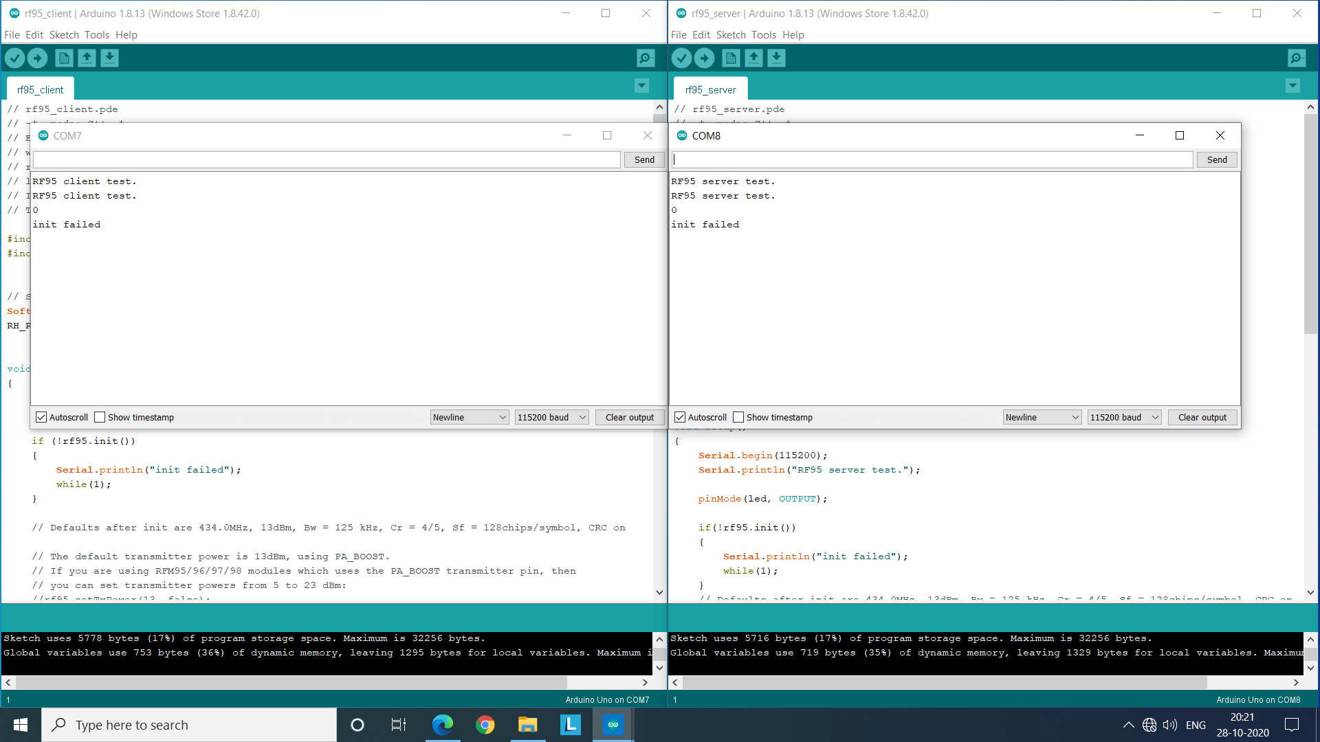
Nope… The same error is coming again (init failed).
Why is the initialisation getting failed?
@tiwari73rajesh can you share the full error log!
@salman sir, this is the error I’m getting displayed on the serial monitor, despite unplugging the RX and TX cables before uploading the sketch and then again plugging them in after the sketch has been uploaded:
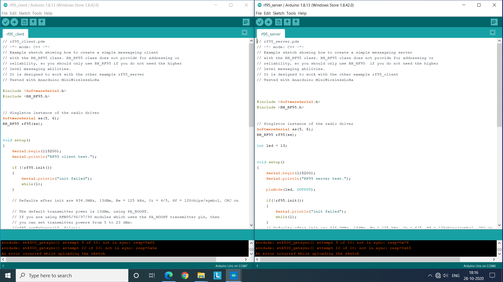
And, these are the error logs (or messages) I’m getting during upload failure, despite connecting the RX of radio to the TX of arduino, and the TX of radio to the RX of arduino:
Error messages of rf95_client: Arduino: 1.8.13 (Windows Store 1.8.42.0) (Windows 10), Board: “Arduino Uno”
Sketch uses 5778 bytes (17%) of program storage space. Maximum is 32256 bytes.
Global variables use 753 bytes (36%) of dynamic memory, leaving 1295 bytes for local variables. Maximum is 2048 bytes.
avrdude: stk500_getsync() attempt 1 of 10: not in sync: resp=0x52
avrdude: stk500_getsync() attempt 2 of 10: not in sync: resp=0x46
avrdude: stk500_getsync() attempt 3 of 10: not in sync: resp=0x39
avrdude: stk500_getsync() attempt 4 of 10: not in sync: resp=0x35
avrdude: stk500_getsync() attempt 5 of 10: not in sync: resp=0x20
avrdude: stk500_getsync() attempt 6 of 10: not in sync: resp=0x63
avrdude: stk500_getsync() attempt 7 of 10: not in sync: resp=0x6c
avrdude: stk500_getsync() attempt 8 of 10: not in sync: resp=0x69
avrdude: stk500_getsync() attempt 9 of 10: not in sync: resp=0x65
avrdude: stk500_getsync() attempt 10 of 10: not in sync: resp=0x6e
An error occurred while uploading the sketch

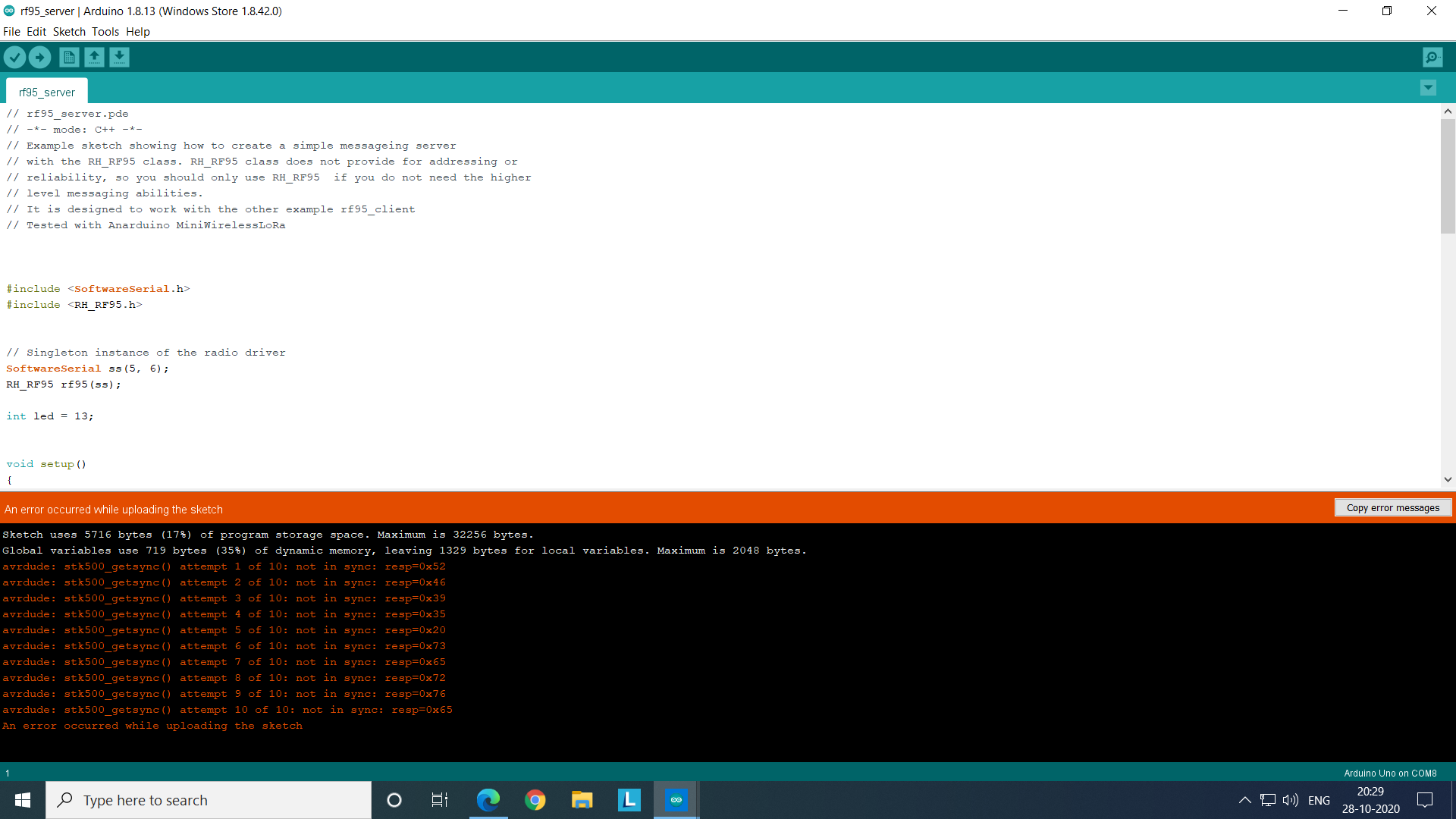
Error messages of rf95_server: Arduino: 1.8.13 (Windows Store 1.8.42.0) (Windows 10), Board: “Arduino Uno”
Sketch uses 5716 bytes (17%) of program storage space. Maximum is 32256 bytes.
Global variables use 719 bytes (35%) of dynamic memory, leaving 1329 bytes for local variables. Maximum is 2048 bytes.
avrdude: stk500_getsync() attempt 1 of 10: not in sync: resp=0x52
avrdude: stk500_getsync() attempt 2 of 10: not in sync: resp=0x46
avrdude: stk500_getsync() attempt 3 of 10: not in sync: resp=0x39
avrdude: stk500_getsync() attempt 4 of 10: not in sync: resp=0x35
avrdude: stk500_getsync() attempt 5 of 10: not in sync: resp=0x20
avrdude: stk500_getsync() attempt 6 of 10: not in sync: resp=0x73
avrdude: stk500_getsync() attempt 7 of 10: not in sync: resp=0x65
avrdude: stk500_getsync() attempt 8 of 10: not in sync: resp=0x72
avrdude: stk500_getsync() attempt 9 of 10: not in sync: resp=0x76
avrdude: stk500_getsync() attempt 10 of 10: not in sync: resp=0x65
An error occurred while uploading the sketch
Could there be a fault in the sketch?
No, Since the compilation completed successfully, there is less chance of bug in sketch.
Can you share the serial monitor Screen Shots?
This error due to the IDE can’t upload the code on Arduino,
- Check your USB Cable
- Check your Arduino with the example blink sketch
- Disconnect all wire and try uploading the sketch only
try these steps and let me know.