- What happens if you use “STM32CubeProgrammer” instead of STM32CubeIDE to upload sketches?
- Is there an operation in the STM32CubeIDE to start running the sketch after uploading it? Are there any breakpoints set?
- Are you familiar with the operation of STM32CubeIDE?
- I tried to upload the program using STM32CubeProgrammer but, it is displaying the same output.
- No if we upload program, it start automatically.
- I tried to upload the program using STM32CubeProgrammer but, it is displaying the same output.
- Has “reset” been removed?
- Is the STM32CubeIDE closed?
- ST-Link VCC is not connected anywhere?
- What happens if you disconnect the ST-Link after uploading and run it with only the USB connected?
- No, if I remove the reset button, it does not connect with Stm32Cubeprogrammer.
- yes, Stm32cubeide was closed.
- No, ST-Link VCC is not connected anywhere.
- The output is same(After radio Set RFSwitchTable).
- No, if I remove the reset button, it does not connect with Stm32Cubeprogrammer.
My ST-Link can upload without connecting a reset. Press the reset button on LoRa-E5 to connect.
Is “LoRa-E5-HF ” printed on the front of your LoRa-E5 mini package?
I don’t have the actual item in front of me, so I don’t know any more about it. Sorry I can’t help you.
Maybe someone else reading this thread can help.
I am wondering what would happen if you use the same ST-Link that I am using.
LoRa-E5 mini may actually have the firmware rewritten according to the laws of your area of use.
Yes “LoRa-E5-HF” is printed on my LoRa module.
I have a feeling that there is a problem with your use of ST-Link. There is something you have not tried yet, but this is a risk. Please read your ST-Link manual carefully before doing so.
- If TVCC is a function to supply power to the target device, then the LoRa-E5 is already powered by the USB connector and should not be connected.
- If the function is to detect the target supply voltage, then TVCC should be connected to 3.3V pin on LoRa-E5.
edit:
TVCC means TargetVCC, and I see many articles that say it won’t work unless it is connected. However, I am not sure if your ST-Link is the same.
Hello,
I tried the example of transmit data from Radio library. And it is working fine. But when i am using the receiving code, it stuck in the radio.begin() .
Code for receiving data
/*
   RadioLib STM32WLx Receive with Interrupts Example

   This example listens for LoRa transmissions and tries to
   receive them. Once a packet is received, an interrupt is
   triggered. To successfully receive data, the following
   settings have to be the same on both transmitter
   and receiver:
    - carrier frequency
    - bandwidth
    - spreading factor
    - coding rate
    - sync word

   This example assumes Nucleo WL55JC1 is used. For other Nucleo boards
   or standalone STM32WL, some configuration such as TCXO voltage and
   RF switch control may have to be adjusted.

   For default module settings, see the wiki page
   https://github.com/jgromes/RadioLib/wiki/Default-configuration#sx126x---lora-modem

   For full API reference, see the GitHub Pages
   https://jgromes.github.io/RadioLib/
*/

// include the library
#include <RadioLib.h>

// no need to configure pins, signals are routed to the radio internally
STM32WLx radio = new STM32WLx_Module();

// set RF switch configuration for Nucleo WL55JC1
// NOTE: other boards may be different!
//       Some boards may not have either LP or HP.
//       For those, do not set the LP/HP entry in the table.
static const uint32_t rfswitch_pins[] =
                         {PA4,  PA5, RADIOLIB_NC, RADIOLIB_NC, RADIOLIB_NC};
static const Module::RfSwitchMode_t rfswitch_table[] = {
  {STM32WLx::MODE_IDLE,  {LOW,  LOW}},
  {STM32WLx::MODE_RX,    {HIGH, LOW}},
  // {STM32WLx::MODE_TX_LP, {HIGH, HIGH, HIGH}},
  {STM32WLx::MODE_TX_HP, {LOW,  HIGH}},
  END_OF_MODE_TABLE,
};

void setup() {
  Serial.begin(9600);

  // set RF switch control configuration
  // this has to be done prior to calling begin()
  radio.setRfSwitchTable(rfswitch_pins, rfswitch_table);

  // initialize STM32WL with default settings, except frequency
  Serial.print(F("[STM32WL] Initializing ... "));
  int state = radio.begin(868.0);
  if (state == RADIOLIB_ERR_NONE) {
    Serial.println(F("success!"));
  } else {
    Serial.print(F("failed, code "));
    Serial.println(state);
    while (true);
  }

  // set appropriate TCXO voltage for Nucleo WL55JC1
  state = radio.setTCXO(1.7);
  if (state == RADIOLIB_ERR_NONE) {
    Serial.println(F("success!"));
  } else {
    Serial.print(F("failed, code "));
    Serial.println(state);
    while (true);
  }

  // set the function that will be called
  // when new packet is received
  radio.setDio1Action(setFlag);

  // start listening for LoRa packets
  Serial.print(F("[STM32WL] Starting to listen ... "));
  state = radio.startReceive();
  if (state == RADIOLIB_ERR_NONE) {
    Serial.println(F("success!"));
  } else {
    Serial.print(F("failed, code "));
    Serial.println(state);
    while (true);
  }

  // if needed, 'listen' mode can be disabled by calling
  // any of the following methods:
  //
  // radio.standby()
  // radio.sleep()
  // radio.transmit();
  // radio.receive();
  // radio.readData();
  // radio.scanChannel();
}

// flag to indicate that a packet was received
volatile bool receivedFlag = false;

// this function is called when a complete packet
// is received by the module
// IMPORTANT: this function MUST be 'void' type
//            and MUST NOT have any arguments!
void setFlag(void) {
  // we got a packet, set the flag
  receivedFlag = true;
}

void loop() {
  // check if the flag is set
  if(receivedFlag) {
    // reset flag
    receivedFlag = false;

    // you can read received data as an Arduino String
    String str;
    int state = radio.readData(str);

    // you can also read received data as byte array
    /*
      byte byteArr[8];
      int numBytes = radio.getPacketLength();
      int state = radio.readData(byteArr, numBytes);
    */

    if (state == RADIOLIB_ERR_NONE) {
      // packet was successfully received
      Serial.println(F("[STM32WL] Received packet!"));

      // print data of the packet
      Serial.print(F("[STM32WL] Data:\t\t"));
      Serial.println(str);

      // print RSSI (Received Signal Strength Indicator)
      Serial.print(F("[STM32WL] RSSI:\t\t"));
      Serial.print(radio.getRSSI());
      Serial.println(F(" dBm"));

      // print SNR (Signal-to-Noise Ratio)
      Serial.print(F("[STM32WL] SNR:\t\t"));
      Serial.print(radio.getSNR());
      Serial.println(F(" dB"));

    } else if (state == RADIOLIB_ERR_CRC_MISMATCH) {
      // packet was received, but is malformed
      Serial.println(F("CRC error!"));

    } else {
      // some other error occurred
      Serial.print(F("failed, code "));
      Serial.println(state);

    }

    // put module back to listen mode
    radio.startReceive();
  }
}
Code for transmitting data
/*
  RadioLib STM32WLx Transmit with Interrupts Example

  This example transmits LoRa packets with one second delays
  between them. Each packet contains up to 256 bytes
  of data, in the form of:
  - Arduino String
  - null-terminated char array (C-string)
  - arbitrary binary data (byte array)

  For default module settings, see the wiki page
  https://github.com/jgromes/RadioLib/wiki/Default-configuration#sx126x---lora-modem

  For full API reference, see the GitHub Pages
  https://jgromes.github.io/RadioLib/
*/

// include the library
#include <RadioLib.h>

// no need to configure pins, signals are routed to the radio internally
STM32WLx radio = new STM32WLx_Module();

// set RF switch configuration for Nucleo WL55JC1
// NOTE: other boards may be different!
//       Some boards may not have either LP or HP.
//       For those, do not set the LP/HP entry in the table.
static const uint32_t rfswitch_pins[] =
                         {PA4,  PA5, RADIOLIB_NC, RADIOLIB_NC, RADIOLIB_NC};
static const Module::RfSwitchMode_t rfswitch_table[] = {
  {STM32WLx::MODE_IDLE,  {LOW,  LOW}},
  {STM32WLx::MODE_RX,    {HIGH, LOW}},
  // {STM32WLx::MODE_TX_LP, {HIGH, HIGH, HIGH}},
  {STM32WLx::MODE_TX_HP, {LOW,  HIGH}},
  END_OF_MODE_TABLE,
};

// save transmission state between loops
int transmissionState = RADIOLIB_ERR_NONE;

void setup() {
  Serial.begin(9600);

  // set RF switch control configuration
  // this has to be done prior to calling begin()
  radio.setRfSwitchTable(rfswitch_pins, rfswitch_table);

  // initialize STM32WL with default settings, except frequency
  Serial.print(F("[STM32WL] Initializing ... "));
  int state = radio.begin(868.0);
  if (state == RADIOLIB_ERR_NONE) {
    Serial.println(F("success!"));
  } else {
    Serial.print(F("failed, code "));
    Serial.println(state);
    while (true);
  }

  // set appropriate TCXO voltage for Nucleo WL55JC1
  state = radio.setTCXO(1.7);
  if (state == RADIOLIB_ERR_NONE) {
    Serial.println(F("success!"));
  } else {
    Serial.print(F("failed, code "));
    Serial.println(state);
    while (true);
  }

  // set the function that will be called
  // when packet transmission is finished
  radio.setDio1Action(setFlag);

  // start transmitting the first packet
  Serial.print(F("[STM32WL] Sending first packet ... "));

  // you can transmit C-string or Arduino string up to
  // 256 characters long
  transmissionState = radio.startTransmit("Hello World!");
  Serial.print("transmission: ");
  Serial.print(transmissionState);

  // you can also transmit byte array up to 256 bytes long
  /*
    byte byteArr[] = {0x01, 0x23, 0x45, 0x67,
                      0x89, 0xAB, 0xCD, 0xEF};
    state = radio.startTransmit(byteArr, 8);
  */
}

// flag to indicate that a packet was sent
volatile bool transmittedFlag = false;

// this function is called when a complete packet
// is transmitted by the module
// IMPORTANT: this function MUST be 'void' type
//            and MUST NOT have any arguments!
void setFlag(void) {
  // we sent a packet, set the flag
  transmittedFlag = true;
}

// counter to keep track of transmitted packets
int count = 0;

void loop() {
  // check if the previous transmission finished
  if(transmittedFlag) {
    // reset flag
    transmittedFlag = false;

    if (transmissionState == RADIOLIB_ERR_NONE) {
      // packet was successfully sent
      Serial.println(F("transmission finished!"));

      // NOTE: when using interrupt-driven transmit method,
      //       it is not possible to automatically measure
      //       transmission data rate using getDataRate()

    } else {
      Serial.print(F("failed, code "));
      Serial.println(transmissionState);

    }

    // clean up after transmission is finished
    // this will ensure transmitter is disabled,
    // RF switch is powered down etc.
    radio.finishTransmit();

    // wait a second before transmitting again
    delay(1000);

    // send another one
    Serial.print(F("[STM32WL] Sending another packet ... "));

    // you can transmit C-string or Arduino string up to
    // 256 characters long
    String str = "Hello World! #" + String(count++);
    transmissionState = radio.startTransmit(str);

    // you can also transmit byte array up to 256 bytes long
    /*
      byte byteArr[] = {0x01, 0x23, 0x45, 0x67,
                        0x89, 0xAB, 0xCD, 0xEF};
      transmissionState = radio.startTransmit(byteArr, 8);
    */
  }
}
Has the ST-Link problem been resolved?
Serial monitor output for receiving code. It appears to be working.
14:47:41.808 → [STM32WL] Initializing … success!
14:47:41.872 → success!
14:47:41.872 → [STM32WL] Starting to listen … success!
…
…
14:47:42.300 → [STM32WL] Received packet!
14:47:42.333 → [STM32WL] Data: Hello World! #110
14:47:42.367 → [STM32WL] RSSI: -102.00 dBm
14:47:42.400 → [STM32WL] SNR: 8.25 dB
14:47:43.513 → [STM32WL] Received packet!
14:47:43.545 → [STM32WL] Data: Hello World! #111
14:47:43.578 → [STM32WL] RSSI: -102.00 dBm
14:47:43.609 → [STM32WL] SNR: 8.25 dB
14:47:44.692 → [STM32WL] Received packet!
Yes, it is working fine.
Hi,
I’m building P2P communication using two LoRa-E5-HF modules. The C++ examples above work fine, but in my case one of the modules will run factory AT firmware. I configured both ends to have matching params like frequency, SF, BW, preamble size, etc. The module with AT firmware can receive packets from the one running C++ code based on RadioLib, but with the same settings it doesn’t work in the other direction.
Not all settings are exposed by AT firmware, so e.g. header type, coding rate cannot be set, I’m just guessing these. Does anyone have any suggestion on what combination I should try?
Update: The device which is sending the lost packets is connected to UART2 of an ESP32 dev board. It seems that the problem is caused by ESP32 being too noisy. I tested with two devices with factory AT firmware; one of these connected to ESP32, the other to the serial port of my PC. Even if I swap the two identical devices, it’s always the one connected to ESP32 which is unable to send.
Hey ! Hope you’ll see this message.
I have the exact same issue as you, my Wio E5 mini dev stucks at radio.begin(), though the only difference is that it’s both in receive & transmitting.
Everything else works (blinking, writing to serial)
I’m using ST Link v2 with Arduino IDE and selected the Lora E5-mini board.
I have absolutely no idea why it’s stuck at radio.begin()
1 Like
Check out these new devices should be able to program the XIAO directly
FYI
1 Like
Hey,
I already bought Wio-E5 Mini dev board and Wio E5 Dev kit
I can upload firmware to them, but can’t make them transmit or receive… (both stuck at radio.begin whatever I do)
So I don’t think buying another device will help me haha
Oren,
Is POST#8 at the link below helpful?
“Programming LoRa-E5 with Arduino, LoRa-E5 mini Point to Point Comminucation over 24 km - #8 by msfujino”
Hello, no it’s the same. Stuck at radio.begin() with radiolib.
I tried with both Wio-E5 mini dev and Wio E5 dev kit, both are stuck at radio.begin.
Adding debugging to the RadioLib (using 6.4.0 but same issue occurs with 6.6.0 and 7.2.1), I know it’s because the chip isn’t found, throwing error RADIOLIB_ERR_CHIP_NOT_FOUND (-2)
Can you post your code that stops at radio.begin()?
I can try it here.
Yes, here you go (it’s essentially your P2P_verify script without SD and display code)
SX126x_PingPong.zip (3,1 Ko)
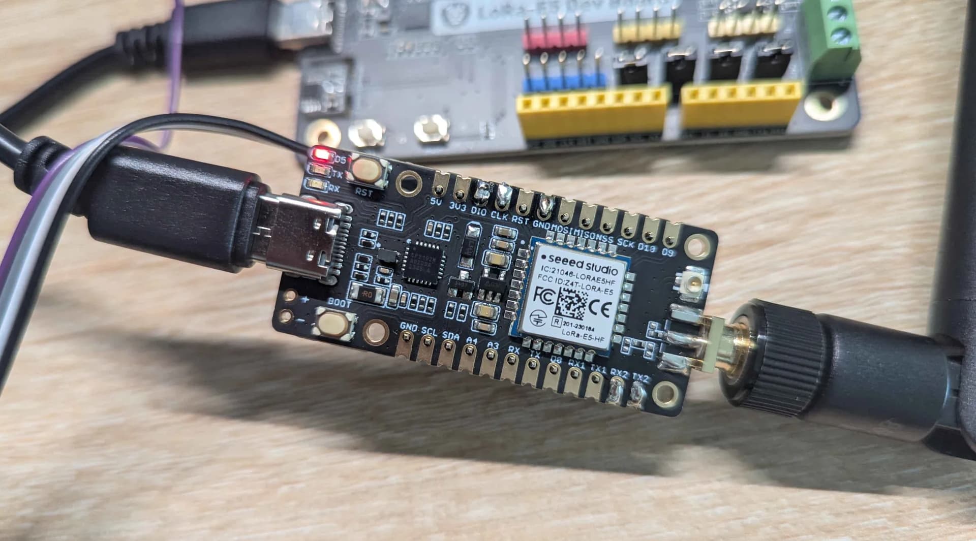
This is the board you are using, right?