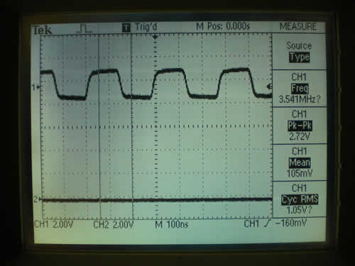
Attached are pictures of a 3.55Mhz square wave signal from a function generator. All connections are same as previous post, except that a function generator is generating the square wave signal.
-
The first picture shows the Tek view by itself with both the tee’d BNC cables connected and the Quad MCX adapter disconnected. The rounded edges are due to the stray capacitance of the cabling which does not match the stray capacitance of a standard 1x probe.
-
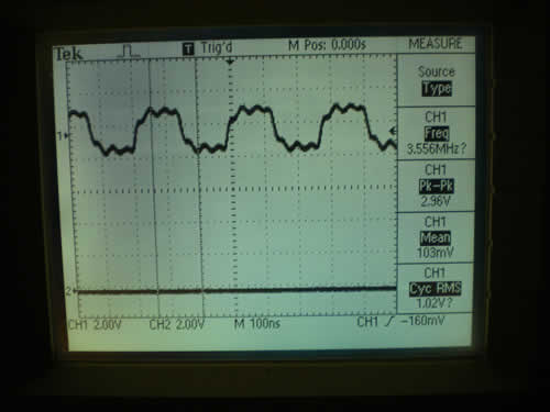
Second picture shows the Tek view with Quad connected.
-
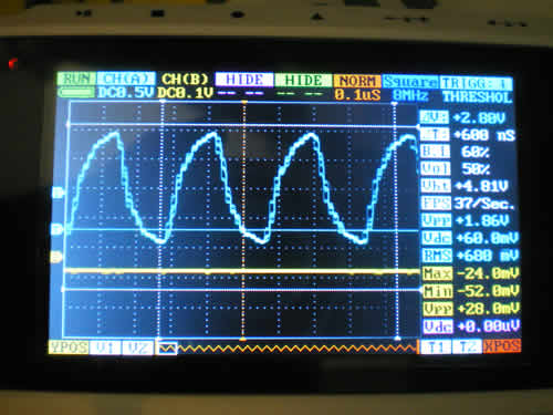
Third picture shows Quad view with both connected. Please note that calibration has not been conducted on the 0.5V scale. the waveform is the subject of concern here, not the amplitude. My original Engineering model Quad presented with a much better waveform for the same condition as this Beta model. Note that this is a multiple sweep display because the camera shutter allows more than one sweep to be viewed in this picture. This accounts for the strange look due to multiple display sweeps.
-
Fourth picture can be found on the next post, because only 3 attachments are allowed. This picture shows the Quad after being disconnected from Quad MCX adapter and shows the measured remnants from picture #3. This is very disturbing because it is a false measurement in real-time, this is why I suspect all measurements when changing the input signal.
Conclusions:
a. Quad stray capacitance is limiting the input signal and causing Tek measurement errors.
b. Measurement values are not properly updated when signal trigger is lost.
b. Those boxes in picture 3 are due to multiple sweeps. One sweep shows steps, not boxes. What is interesting is that these steps are in the same time domain as the switching noise of the interlace mode. This may indicate that display issues are causing these steps in the interleave mode, and not the interleave mode itself.