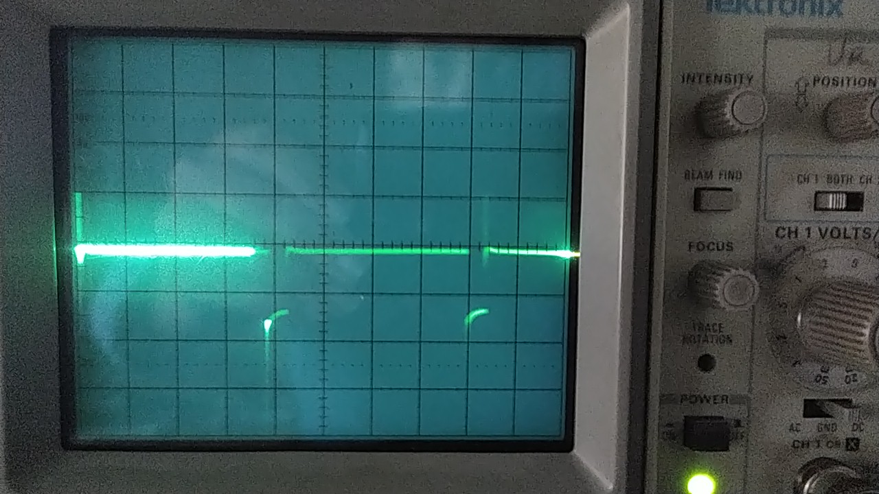
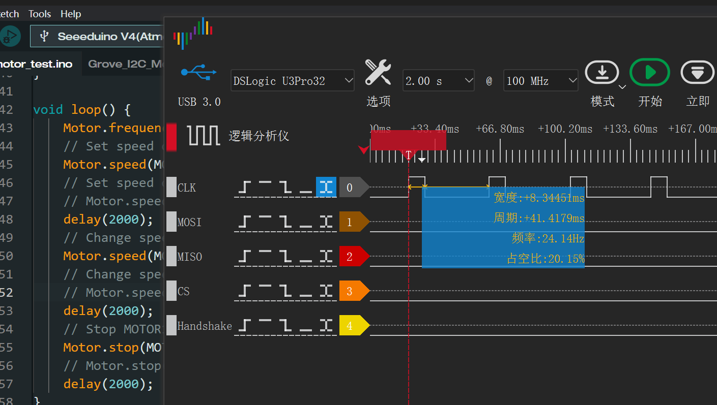
I was able to hear a low frequence noise so I connected an oscilloscope to the driver (without the motor for easier reading).
The period of the signal is 40ms so the frequency is 25Hz.
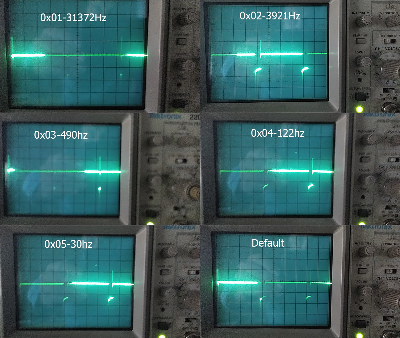
If I uncomment the line Motor.frequence, and change the value from 0x05 to 0x01 (supposed to be 31372Hz, 3921Hz,490Hz, 122Hz, 30Hz according to the library), the PWM frequency is still 25Hz but the PWM ratio change a lot.
I performed some test on several cards with same results.
Is there a way to correct this? I think the problem is on STM32 side.
In this state, this card is not suitable for fast response application: position adjustment with an encoder in my case.
I can provide the oscilloscope screenshot for better understanding.
Hello & Welcome, benp
Can you show more of the code and how it’s connected? and what it’s connected to?
what board are you using and most important is how you power the whole thing, can you show a schematic or picture. Others will comment also with more to go by.
have you looked at this link for pointers.,
Thank you PJ_Glasso
Motor control with the encoder is not the problem. My problem is slow motor response to command because:
I2C library is too slow (solved with library modification)
PWM frequency is too slow: 40ms period (not solved)
Here is the context:
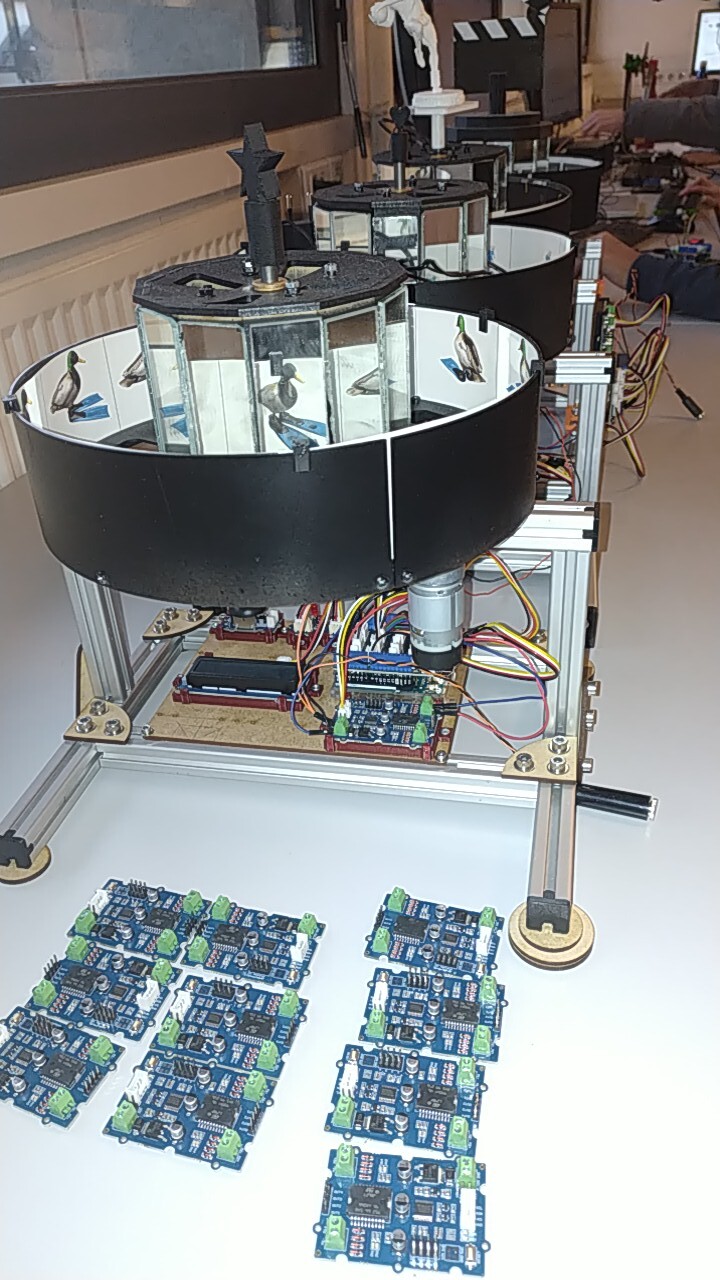
We try to find an improve solution for EMG30 motor+encoder+arduino+Arduino motor shield L298.
Here is one of the box which we use with our 800 students:
The improved solution (in test) is made with an I2C Motor Driver V1.3
Why migrate: I2C free a lot of port for more complex projets and we can use interrupt pin 2 & 3(pin 3 is used by arduino motor shield).
The old design motor control can be done with this Arduino program (proportional control):
#include <Encoder.h>
Encoder myEnc(2, 5);

long commande = 0;
long Position;
int erreur;
int consigne = 180;
float kp = 20;

void setup() {
  pinMode(12, OUTPUT);    //pin Direction
  pinMode(3, OUTPUT);    //pin PWM
}

void loop() {
  Position = myEnc.read();
  erreur = consigne - Position;
  commande = kp * erreur;
  moteur(commande);
}

//Commande du moteur
void moteur(int vit) {
  if (vit > 255) vit = 255;
  if (vit < -255) vit = -255;
  analogWrite(3, abs(vit));
  digitalWrite(12, (vit > 0));
}
The new design can be control with this program with a library modification:
This motor control can only be performed with library modification: remove the delay(4) in the library (point one solved at the beginning of this message). Without this, motor control is impossible
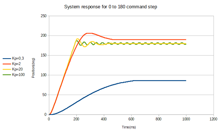
Note that Kp=40 in the old design and Kp= 0.8 in the new design!
The Kp value are obtained with Ziegler–Nichols method
Why such a difference? Because PWM is too slow. The result is very poor performance compared to old design: high error and slow speed: this motor control is not usable in real projects.
Next pictures/text in next message: I cannot post more as new user!
Why is 40ms not good: because our oscillation period Tu=45ms (typical) with EMG30+L298 (see Tu meaning in the Ziegler–Nichols method link.
Here are the response curves for old design:
This is for my first post program: Motor 2=10% and default Motor.frequence
The time scale is 10ms so the period of pwm is 4x10ms=40ms (25 Hz)
I will post the other motor.frequence oscilloscope screenshot when I will have the right to post several picture.
I think there is a bug in STM32 embedded in the grove DC motor but I didn’t understand the On-Chip Firmware for I2C motor driver to do it myself.
Hi there,
Yes looks slow,I seem to remember something like
" Wire1.setClock(400000UL); //set 400kHz"
see if there is something like that available.
HTH
GL PJ
Default Arduino UNO I2C frequency (100Khz) is not the problem: the loop time is 0.8 ms with the improved library (without delay(4) see in previous post).
The problem is the PWM frequency on the motor output: it is 490 Hz(2ms) on Arduino UNO+Arduino motor shield and 25Hz (40ms) on Grove Motor driver V1.3
The STM32 microcontroler on the grove motor driver generate the 25Hz PWM frequency.
motor.frequence (in the library) should change the pwm frequency but it changes only slighly the pwm ratio. See the oscilloscope capture:
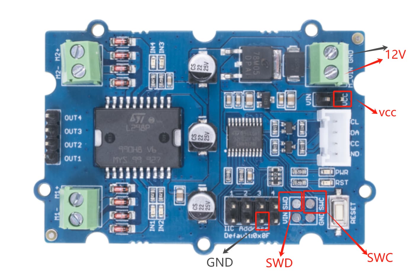
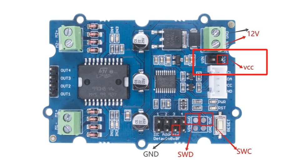
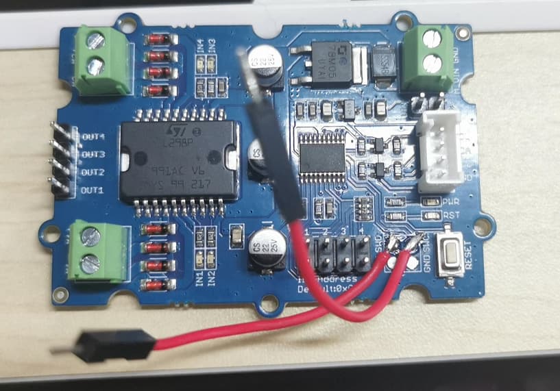
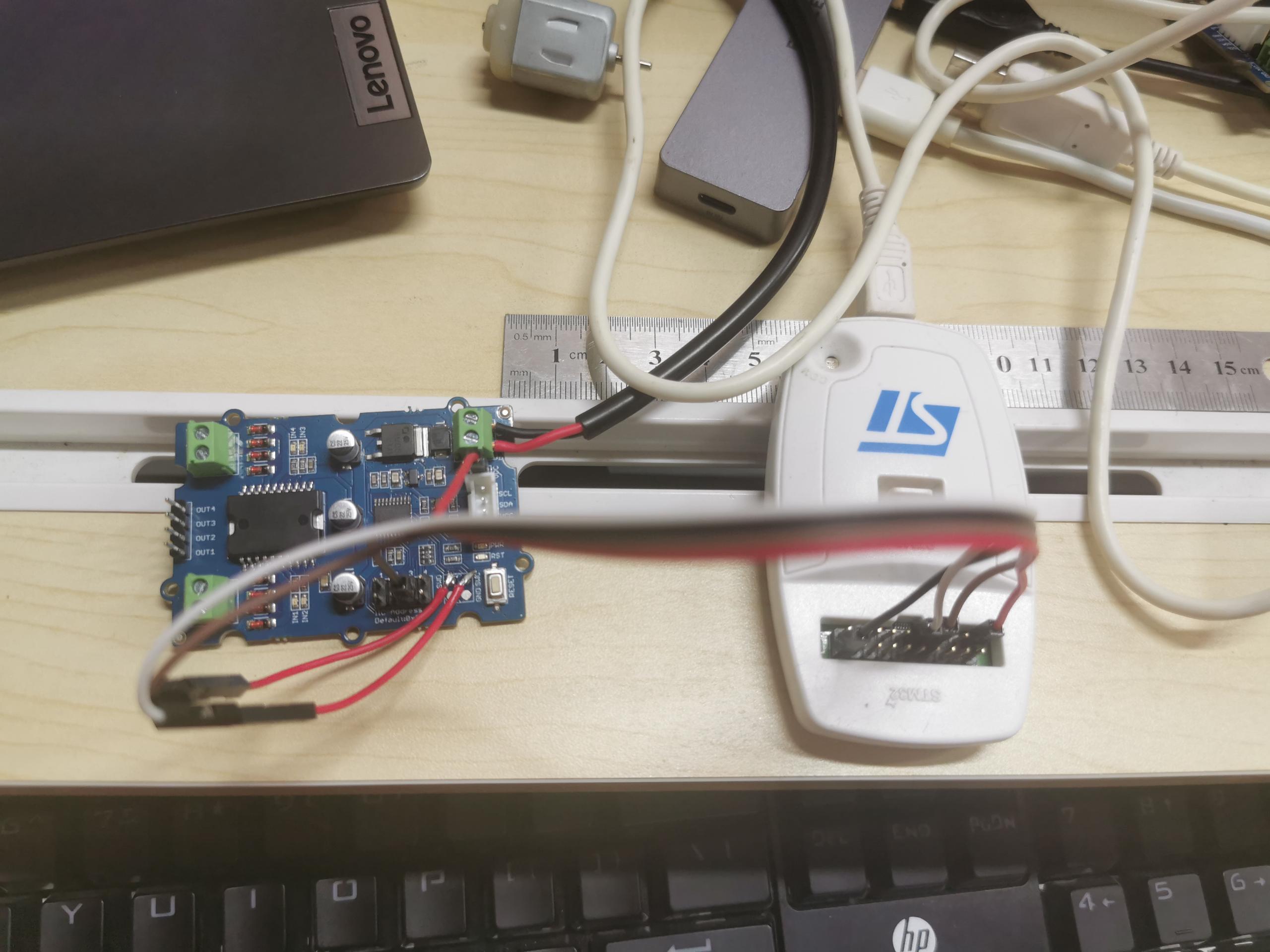
Is it possible to reprogram the STM32 with a ST-LINK V2 on the SWD interface? Do you have an easy connection method?
Does somebody know where is the firmware? If not, I need to write everything from scratch!
I apologize for any inconvenience caused. We have received your feedback, and we are currently discussing it internally. Once we have a resolution, we will reply to you in this thread promptly.
We are waiting for your solution. We have a lot of Grove - I2C Motor Driver (L298P) we can’t use. See above picture: Drivers in machines we can’t use and drivers on stock.
Regards,
We still have no news from seed studio.
We will shortly return for money back all our Grove - I2C Motor Driver (L298P) to our French distributor Farnell for “product does not match the specifications”.
Sorry, dear. Grove - I2C Motor Driver (L298P) and Grove - I2C Motor Driver V1.3 has the same chip so that they use the same library
Today, I will personally conduct some actual tests in an effort to try and reproduce and resolve the problem. We truly regret any inconvenience this may have caused you. Thank you once again for your patience and understanding.
Currently, our R&D team is working diligently to update the new STM32 firmware. We will definitely provide you with feedback on this topic when the latest STM32 firmware library is available.
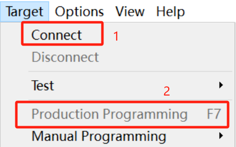
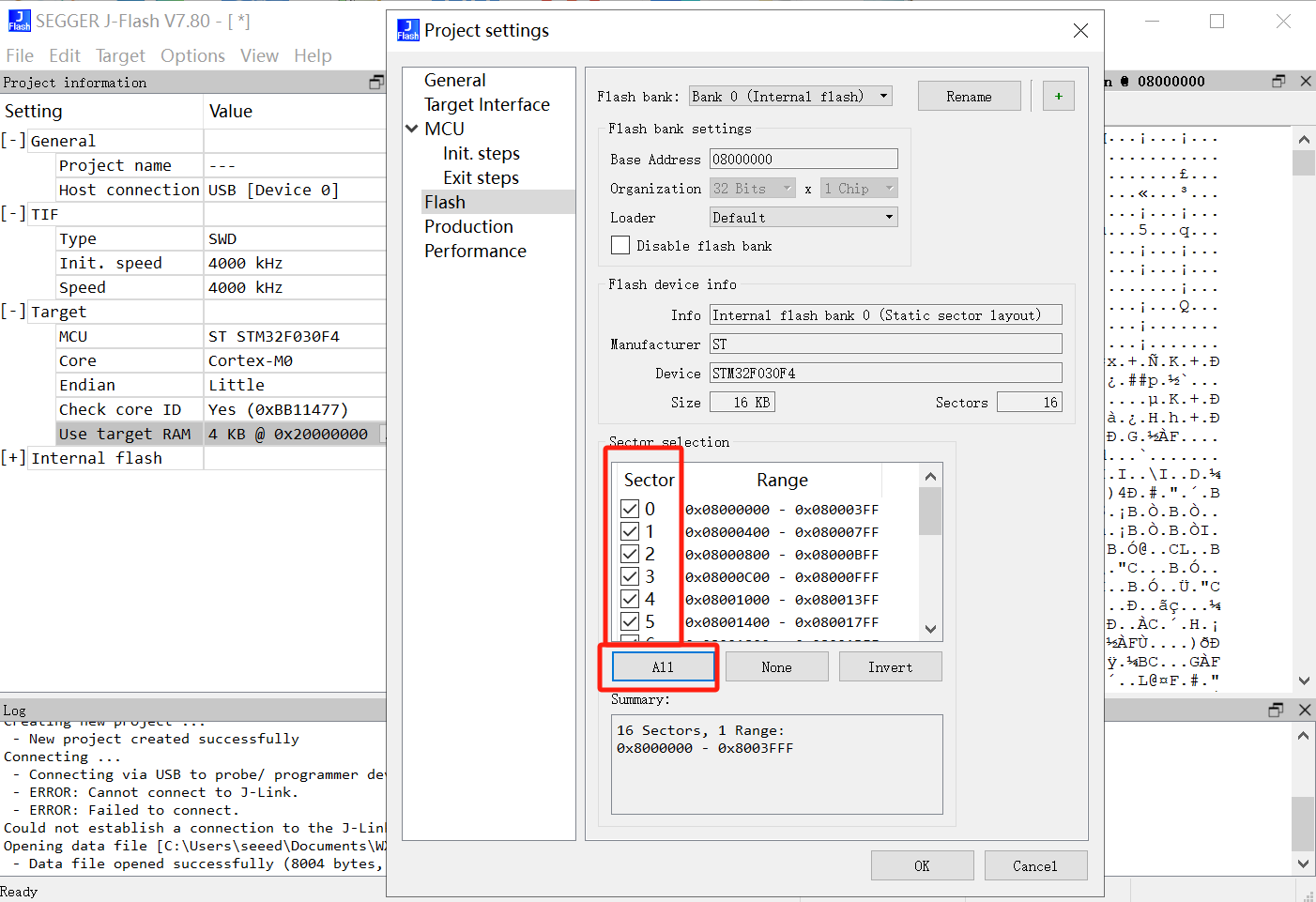
FAQ
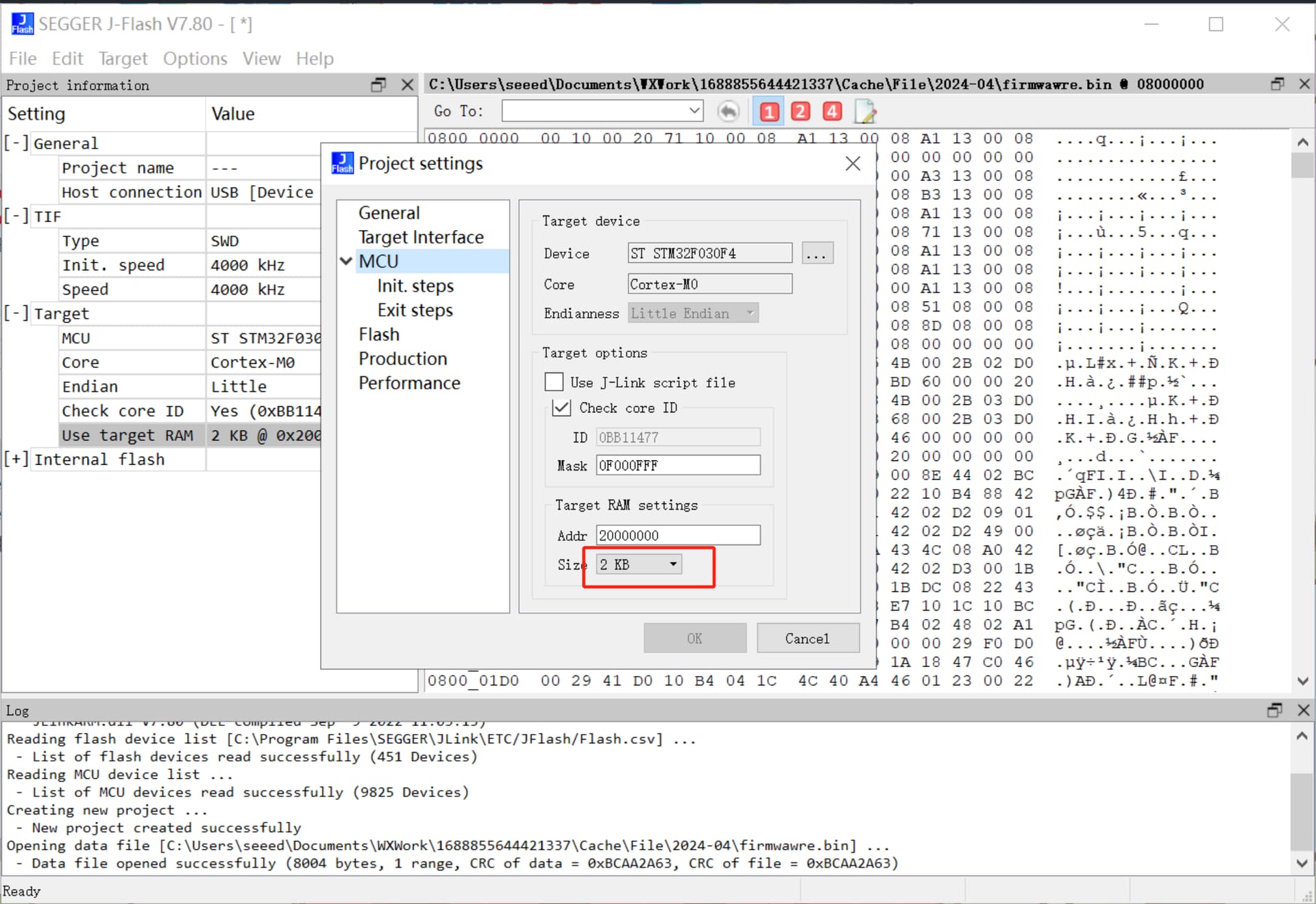
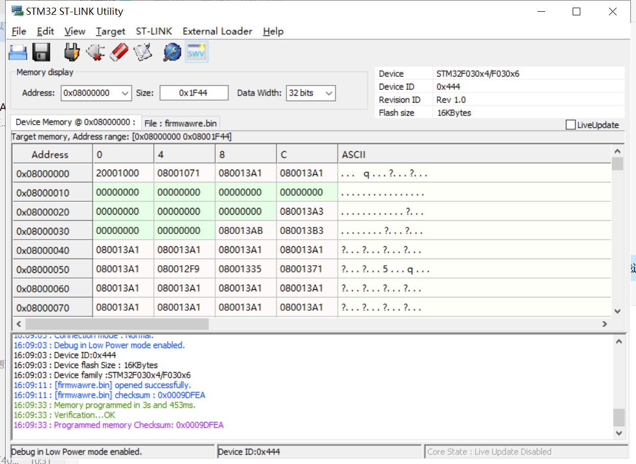
If the operation fails, please check whether all the above configurations have been properly set. Verify that all Sectors below are checked. All sectors need to be selected.
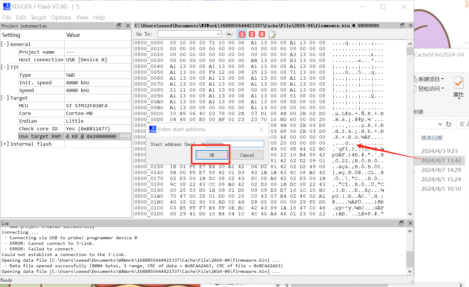
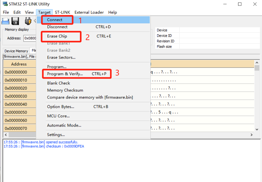
If your wiring is correct, clicking on Connect will directly recognize your current chip without additional checking.
Then Erase Chip and Program & Verify
You must connect the 3.3V, just as indicated in the picture. You need to connect the VCC of the ST-link and the Grove - I2C Motor Driver (L298P) together.