
Hi Slimfish and ESP,
Nice detailed post! My comments:
The DSONANO is not a laboratory instrument with high bandwidth. If the sampling rate is 1 Msps then the max usable input is <500kHz. The internal ADC in the ST uC (or any ADC) generally cannot resolve the number of bits claimed. The ENOB with noise factored in the calculations, and by empirical measurement, is lower by 2 or more bits (i.e. 14 bit -> 12 bit, 16 bit ->14 bit, etc.) of reliable measurement. This impacts not only the S/N but the resolution out of a maximum 3 volts. The resolution determines the offset which can cause an error in the signal measured. Essentially, the offset numbers you calculated are much, much smaller the ADC can resolve.
Note that most commercial scopes (Tektronix, Agilent, etc.) costing less than $3000 have only 8 bits of amplitude resolution (i.e. “Y” or “Vertical” resolution).
BANDWIDTH
As for the GBW of the amplifiers, note that they all vary with the gain of the PGAs. The PGA113 can have a gain of 50 and still exceed the DSANANO bandwidth. I guess if you want to measure micro volts, than this will not be sufficient. I can’t see using the DSONANO for use with very small signals because of the total lack of shielding, the input connector, and the probe arrangement. The DSONANO can be useful from a few HZ to perhaps 499 kHz with input signals greater than 10 mV. With 10 mV input signals the accuracy will not be very useful, but signal shape can be analyzed. To measure signals with reasonable accuracy, the input should be greater than 50-100 mV.
OFFSET
As for offset, refer to U5A in the DSONANO. The sole function of this circuit is to DC level shift the signal. The input to this circuit is via R15. The uC outputs a PWM here, which is integrated by R15, C12 and R16, C13 into a variable (depending on PWM) DC voltage to pin 3 of U5A. U5A functions as a buffer changing the DC level of the input signal from U5B before it goes to the uC ADC. If you replace U5 with a PGA, then the PGA has to have a variable offset input, which is pin 4 Vref on the PGA113. This is necessary even if the input is DC coupled to compensate for any offset and is probably also used for vertical positioning of the waveform on the LCD display.
COUPLING
Perhaps I was not clear about AC / DC input coupling. I suggest ONLY AC input coupling for the reasons I mentioned. DC coupling for the full range of inputs would not easily fit within the DSONANO (the complexity of the attenuator, requirement for +/- supply, level shift to match the 3 V ADC, etc.). A simple1nF capacitor in series with the 10 or 100 kOhm input resistor would work down to a few HZ.
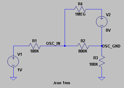
INPUT IMPEDANCE
The resistor I mentioned in the input is not to raise the input impedance, but to offer current limiting for the protection diodes in the PGA113. This is a very simple and inexpensive input protection circuit in case the probe is connected to a high voltage. The input impedance of the PGA113 is 10 GOhm (10,000 MOhm) with 5 pF capacitance. Changing the gain does not change this. Since most oscilloscope probes expect to connect to 1 MOhm , 5pF load, a 900 kOhm resistor (assuming a 100 kOhm input series resistor) is necessary from the input pins (2, 3) to ground. This is how the input impedance is defined. Note that there will be some small pF capacitors needed here to make sure the impedance is flat across the usable bandwidth. Most of the other PGAs have much, much lower input impedance and much, much higher capacitance.
10 CHANNEL INPUT (PGA117)
This was in response to a few posters who asked about the possibility. You are correct that this would not make the DSONANO a 500 MHz Logic Analyzer, but limited to perhaps 100 to 300 kBs. I think that this would not be very useful because of the small screen and low resolution the DSONANO. But if there are people interested in this, it is a possibility. There are USB 8+ channel Logic Analyzer probes with similar performance for about the same price already, and they show the multiple waveforms on the large PC / Laptop / Netbook screen.
AUTO OFF
Perhaps what you need is an external battery pack. Model RC airplanes and helicopters have readily available LiPo batteries about the same size as the DSONANO which could operate it for 20-40 hours continuously. Of course this would more than double the thickness and weight of the DSONANO, cost $20-$40 and require a separate charger $20-$20.
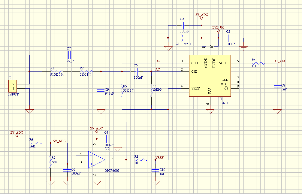
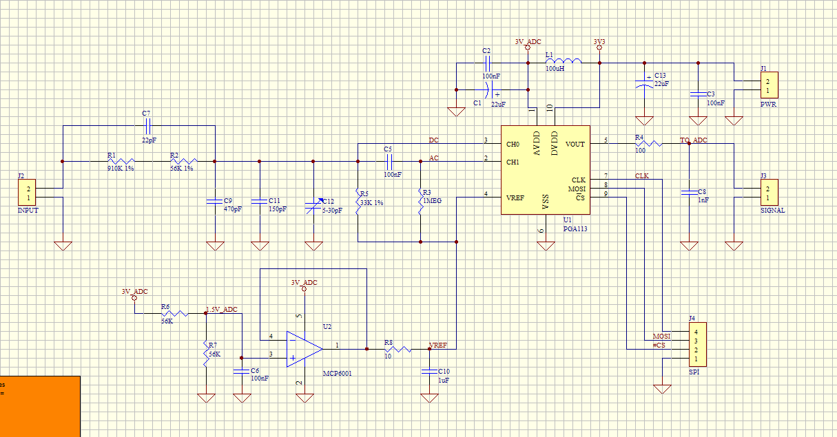
SCHEMATIC from Slimfish of 6-22-2010
A few changes suggested:
• AC Couple both channels.
• Delete the 1 MOhm from IC pin 2. This also allows using a 1 nF or 0.1 nF COG (do not use X7R, X5R, Y5U, etc.) on pin2.
• R1, R2, C7 need to be 805 or 1206 for >200V capability. C7 and C? (47pF to GND) need to be COG types
• Delete C8, the ADC has enough capacitance. If a low pass filter is desired here, increase the value of the 100 Ohm resistor and use the input capacitance of the ADC to calculate R.
• Delete the entire Vref section (OpAmp and related parts). Connect pin 4 of the PGA113 to the same place as U5A pin 3 (R13 - C16 junction) in the current DSONANO.
ESP,
I can help sourcing any parts. TI lists inventory here: focus.ti.com/docs/prod/folders/print/pga113.html
As I write this, The PGA113 is in stock at:
Avnet= 250 , Digi-Key= 98, Newark=139 , Farnell Asia= 519, Farnell Europe= 499 and Mouser= 86
The PGA 112 is almost the same part, but with Binary gain steps. Since this is for a DSO, I thought the simple 1-2-5 gain steps of the PGA113 would be more appropriate. The same vendors listed above have PGA112 in stock at larger quantities. I suggest you contact TI Asia. They can get you free samples and help with buying for production.
Shazam


 I saw the DSO demonstration in my arduino course. It’s very usefull to work. the DSO is pratical and good to work fine to automation projects.