When resistors are introduced, it is explained that they can be either in series or in parallel configuration. In series means that the are traversed by the same current and one of the terminals of each resistor is connected to the other’s terminal( I am saying that because there can be two resistors in a circuit that are traversed by the same current but not be in series).
In parallel means that the terminals of two resistors are connected to each other and to a wire/conductor that is equipotential while the other two terminals are also interconnected to a wire that equipotential as well but at a different potential than the other wire. The voltage drop across both resistors is the same.
I checked a website that compared resistors in parallels and series.I believe that two or more resistors can be connected in such a way that they are not in series neither in parallel, i.e. they don’t have the same voltage drop and are not traversed by the same current…Is that correct? I think so… Do you have any good example?
One common example of a combination arrangement is a circuit with resistors arranged in a “star” or “delta” configuration.
In a star configuration, resistors are connected at a central node, with one terminal of each resistor connected to the central node and the other terminal connected to different points in the circuit. This arrangement doesn’t fit the definition of series or parallel because the current flowing through each resistor is not the same, and the voltage drop across each resistor may vary.
Hi there,
So I’ll byte,
You can’t refute the laws of Physics , even in electronics…
Kirchhoff’s First Rule
Kirchhoff’s first rule (the
junction rule
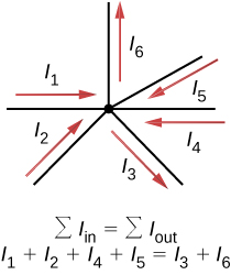
) applies to the charge entering and leaving a junction (Figure 10.4.210.4.2). As stated earlier, a junction, or node, is a connection of three or more wires. Current is the flow of charge, and charge is conserved; thus, whatever charge flows into the junction must flow out.
Figure 10.4.210.4.2: Charge must be conserved, so the sum of currents into a junction must be equal to the sum of currents out of the junction.
Although it is an over-simplification, an analogy can be made with water pipes connected in a plumbing junction. If the wires in Figure 10.4.210.4.2 were replaced by water pipes, and the water was assumed to be incompressible, the volume of water flowing into the junction must equal the volume of water flowing out of the junction.
Ah’ , there’s a second one too. if you want more , look here.