DSO Quad bandwidth

Today I attempted to do some Quad measurements (fresh out of the box sys 1.31, app 2.30. fpga?? (I wanted a base-line before I changed anything)) but I ran into a couple of snags:

  1. All my waveform displays appear to be 1/10 of the sine wave input signal. Where do you set the 1x or 10x probe type? I can’t find a menu choice for that in the Quad Manual 0.91b. Is there a 10x probe selection option?

  2. The Auto trigger mode is very flaky. It has trouble finding sync and many times displays garbage when it appears to be synched, but after a few seconds it may lock in and display properly. If it doesn’t lock in properly, then you must move the trigger level out of the signal and then bring it back and try again. Success rate appears to be about 30%

  3. The Normal mode trigger on the other hand appears to lock properly and always displays an appropriate waveform.

  4. The Quad-measured Vpp does seem to track the Quad displayed waveform amplitude properly, but the Quad-measured Vpp appears to be off by a factor of 20, 1/20th of the actual input signal; or to put another way, 1/2 of the 1/10 amplitude observed waveform.

  5. All amplitude and frequency measurements of the input signal are conducted off a TEE’d BNC cable to a Tektronix TDS-210 60Mhz scope with 1GS/s sample rate. The input to the Quad uses an MCX to BNC adapter and BNC cable from the TEE that also feeds the Tektronix scope.

Once I get this 1/10 issue resolved, then I will conduct accurate bandwidth measurements at 1Mhz increments. My initial findings using only the display results shows the roll-off (-3db)to start between 3 and 4 Mhz and at 10Mhz the amplitude falls to 40% of 1/10th of the input signal. Once again, all these measurements were conducted with sine wave signals.

Found my 1/10 problem to be the 10x setting (by mistake) on the Tektronix. :blush:

The test conditions listed below took about 5 hours:

  1. Quad FW = App 2.35, Sys 1.34, FPGA 2.5, used “Normal” trigger mode for sinewaves, “Auto” trigger mode for calibration DC voltage measurements.
  2. Performed front-end compensation for best waveform as per factory procedures.
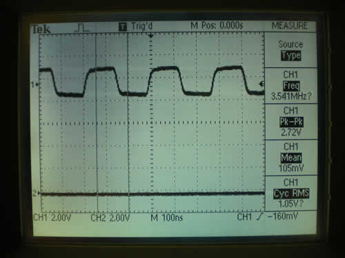
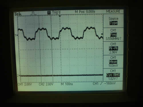
  3. Used Tektronix TDS-210 60Mhz 1GS/S scope to monitor sinewave Quad inputs.
  4. Used a digital multimeter to measure the DC voltages supplied to the Quad.
  5. Using the same DC calibration voltage as an input results in errors. This indicates that the calibration process is not working properly. When you use the same DC voltage to calibrate and then measure, you would expect consistent results, but not the case with these FW versions.
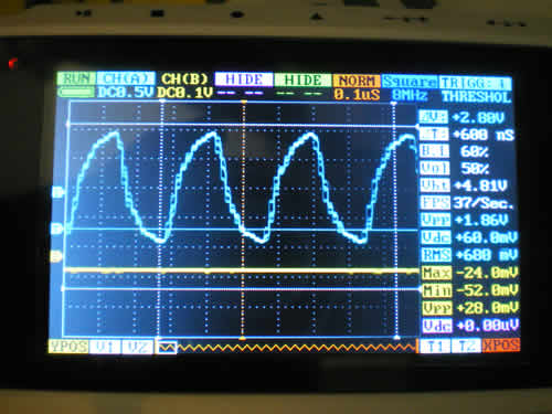
  6. Used the Quad Measure Vp-p function and display waveform for results measurements.
  7. The 50mv and 0.1v scales have bandwidth issues.
  8. The 0.2v scale provides consistent and flat bandwidth for the tested frequencies. :smiley:
  9. My Heathkit IG-102 RF Generator can’t produce output voltage to properly test the remaining scales.

Conclusions:

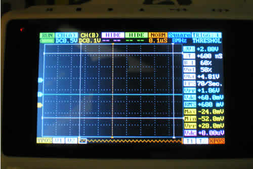
  1. Throughout these tests I never felt comfortable with the Normal Trigger, however the Auto trigger was much worse. It got so bad that I would turn off the Nano for each new test because I didn’t trust that the Vpp was always updating properly. Trigger detection and associated measure updates have been measured and found lacking.
  2. Calibration FW and/or procedures still have issues.
  3. Flat bandwidth can be obtained on the 0.2v/Div scale, although the DC accuracy if different from RF accuracy.
  4. Need to repeat these tests using AC coupling.

Test Results:

[code]Calibrated Chnl-A 50mv/Div with 286mvDC

applied 286mvDC to input and quad = 268mvDC, same with waveform, accuracy = 94%

Tektronix 100Khz sinewave @ 156p-p mv, quad = 110p-p mv, display = 2.2 div = 110p-p mv, accuracy = 70%
Tektronix 1Mhz sinewave @ 156p-p mv, quad = 62p-p mv, display = 1.1 div = 62p-p mv, accuracy = 39%
Tektronix 2Mhz sinewave @ 156 p-p mv, quad = 42 p-p mv, display = .85 div = 42p-p mv, accuracy = 28%
Tektronix 3Mhz sinewave @ 156 p-p mv, quad = 34 p-p mv, display = .7 div = 34 p-p mv, accuracy = 22%
Tektronix 5mhz sinewave @ 152 p-p mv, quad = 28 p-p mv, display = .5 div = 28 p-p mv, accuracy = 18%
Tektronix 10Mhz sinewave @ 152 p-p mv, quad = 18 p-p mv, display = 18 p-p mv, accuracy = 12%

Calibrated Chnl-A 0.1v/Div with 559mvDC

applied 559mvDC to input and quad = 492mvDC accuracy = 88%

Tektronix 100Khz sinewave @ 156p-p mv, quad = 112p-p mv, display = 1.1 div = 112p-pmv, accuracy = 70%
Tektronix 1Mhz sinewave @ 156p-p mv, quad = 100p-p mv, display = 1 div = 100p-p mv, accuracy = 64%
Tektronix 2Mhz sinewave @ 156 p-p mv, quad = 76p-p mv, display = .8 div = 76p-p mv, accuracy = 48%
Tektronix 3Mhz sinewave @ 156 p-p mv, quad = 68p-p mv, display = .7 div = 68p-p mv, accuracy = 44%
Tektronix 5mhz sinewave @ 152 p-p mv, quad = 56p-p mv, display = .6 div = 56p-p mv, accuracy = 37%
Tektronix 10Mhz sinewave @ 156 p-p mv, quad = 36p-p mv, display = .4 div = 36p-p mv, accuracy = 23%

Calibrated Chnl-A 0.2v/Div with 1161mvDC

applied 1161mvDC to input and quad = 984mvDC accuracy = 85%

Tektronix 100Khz sinewave @ 156p-p mv, quad = 120p-p mv, display = .6 div = 120p-p mv, accuracy = 77%
Tektronix 1Mhz sinewave @ 156p-p mv, quad = 120p-p mv, display = .6 div = 120p-p mv, accuracy = 77%
Tektronix 2Mhz sinewave @ 156 p-p mv, quad = 120p-p mv, display = .6 div = 120p-p mv, accuracy = 77%
Tektronix 3Mhz sinewave @ 156p-p mv, quad = 120p-p mv, display = .6 div = 120p-p mv, accuracy = 77%
Tektronix 5mhz sinewave @ 156p-p mv, quad = 120p-p mv, display = .6 div = 120p-p mv, accuracy = 77%
Tektronix 10Mhz sinewave @ 156p-p mv, quad = 120p-p mv, display = .6 div = 120p-p mv, accuracy = 77%
[/code]

Attached are pictures of a 3.55Mhz square wave signal from a function generator. All connections are same as previous post, except that a function generator is generating the square wave signal.

  1. The first picture shows the Tek view by itself with both the tee’d BNC cables connected and the Quad MCX adapter disconnected. The rounded edges are due to the stray capacitance of the cabling which does not match the stray capacitance of a standard 1x probe.

  2. Second picture shows the Tek view with Quad connected.

  3. Third picture shows Quad view with both connected. Please note that calibration has not been conducted on the 0.5V scale. the waveform is the subject of concern here, not the amplitude. My original Engineering model Quad presented with a much better waveform for the same condition as this Beta model. Note that this is a multiple sweep display because the camera shutter allows more than one sweep to be viewed in this picture. This accounts for the strange look due to multiple display sweeps.

  4. Fourth picture can be found on the next post, because only 3 attachments are allowed. This picture shows the Quad after being disconnected from Quad MCX adapter and shows the measured remnants from picture #3. This is very disturbing because it is a false measurement in real-time, this is why I suspect all measurements when changing the input signal.

Conclusions:

a. Quad stray capacitance is limiting the input signal and causing Tek measurement errors.
b. Measurement values are not properly updated when signal trigger is lost.
b. Those boxes in picture 3 are due to multiple sweeps. One sweep shows steps, not boxes. What is interesting is that these steps are in the same time domain as the switching noise of the interlace mode. This may indicate that display issues are causing these steps in the interleave mode, and not the interleave mode itself.
tek view 3.55Mhz tek only.jpg
tek view 3.55Mhz both.jpg
quad view 3.55mhz on both.jpg

Picture #4 goes with previous post.
quad view 3.55Mhz no Quad.jpg

Lygra wrote…

“What is interesting is that these steps are in the same time domain as the switching noise of the interlace mode. This may indicate that display issues are causing these steps in the interleave mode, and not the interleave mode itself”

I think these steps are simply the sample steps. I notice you have both chA and chB on so the unit is not interleaving two sets of samples. To see the interleaving effect, you have to “HIDE” chB. Then you will see the sawtooth effect discussed elsewhere and you will notice an apparent doubling of timebase rate. (which I consider advantageous)

Also apparent on jpg 4 is poor risetime and rounding due to the effect of excessive compensation capacitors discussed earlier. After adjusting my values, I acheive a risetime within 2 sample periods for a 3.5MHz waveform of this amplitude. Go on Lygra, get you soldering iron in the back there!

It is quite possible that those are sampling steps as you stated. If you look at the Nano 50Khz square wave display (attached) you will see 25 steps in the display during one sample time = 1us. This square wave on the Nano is a similar percentage of sample rate as the 3.55Mhz on the Quad. Maybe BenF could comment on the reason for these 25 steps in the Nano. I suspect that they are display update steps. Could the Quad processor be running fast enough that you can’t see it’s display update steps?

I know about the interleave display issues and I am trying to keep this thread on bandwidth topic, that is why that info and associated pictures were not included.

I am going to hold off on the soldering iron while I conduct further testing on the factory issued Quad. :wink:
Nano dsply steps2.jpg

bielec

What hardware did you modify (2.2 or 2.6)?

I have just received my V2.60 DSO Quad and want to get the best performance possible. Is it worth me repeating your mods?

Thanks, Dave

Flyingdave,

My quad was the latest version. If you are using the scope for audio measurements then you won’t notice any improvement by modifying it. The changes improve the upper frequency response and risetime on some of the voltage ranges. You would notice this when using the scope near the upper end of the frequency scale. The mods are fiddly so only attempt them if you are confident using a miniature soldering iron.

Bielec

Thanks. I might give it a try - my main use for the Quad is to look at PAL Video, so it would be good if 4.43 MHz wasn’t too far down (<3db).

What size smd components did you use - most of my stock is 0805, which is probably too big?

Dave

I actually used a mixture of 1206 and 0805 s/m capacitors and for the smaller values I used two pieces of thin single core teflon insulated wire tightly twisted together. This arrangement could be adjusted to give best response.

Hi,

Finally, what’s the BW of the quad ?

Thanks

Well, mine stock had 3dB anywhere from 400kHz to 1Mhz depending on the vertical scale selection.
After patching up the front end the 3dB is now shy of 11Mhz for vertical scale settings. I implemented similar to bielec’s solution (almost the same). The parts I used are low drift resistors (25ppm 0603) and NP0 0603 capacitors.

Anyone has example traces for >2Mhz?
When I hook up a signal (which I think is) >1.x MHz, I dont see the trace (flat), but the frequency counter says 2.x Mhz.

Thanks!

geshsoft

What resistors did you change? bielec only mentioned capacitors.

Thanks

Dave

flyingdave my bad about the resistors - I changed 2 and reverted back to the original as they made no difference, so it is just capacitors really.

ATTENTION, DO NOT BOTHER PERFORMING THE MOD BELOW. I just did it and I still have a damn sine wave on my screen when wave out is set to square wave at 6-8MHz (no improvement). How disappointing. This scope is pretty much worthless above 1 MHz. So much for the quad :frowning:

Noname, a square wave is not a good merit to justify that the mod does nothing.
After the modification the analog BW rolloff is extended to around 10MHz…
In other words, the effective sampling rate of the quad as well as the analog BW of the front end is not good enough to accurately display a square wave at these frequencies. The “sharp edges” of a square wave (higher harmonics) will be attenuated and you will end up mostly with the fundamental.
If you want to be looking at a fully featured square wave you would probably need a scope with way higher analog BW and sampling rate.

Furthermore, although my B channel still worked after the mod, my A channel was nothing but static. I put C73 back on and this got rid of the static but then there was ZERO signal. Nothing but a flat line no matter what. If Seeedstudio has a spare board or suggestions, please let me know.

The mod was not worth doing, and now my A channel is not working. I will probably need to replace an expensive IC and this device was ridiculously expensive as it is. Is there anyone on the planet willing to bothering opening theirs up and risking likelyhood of the plastic case not sealing completely back up again when they could just sell the damn thing and wait for a MUCH better portable scope somewhere down the road?

As far as any signal “improvement” on the remaining B channel, I see basically none. The limitations at 2MHz and above are obvious before and after the mod. Frankly this leads people to believe it is possible to fix the gaping flaws in this device when it is not. I would almost suspect that bielec may have had his silkscreen labeled with components in different positions, but this seems unlikely.

Noname, I agree that the device specs were overstated - both the analog BW and sampling rate.

However, I disagree that the mod posted by bielec is misleading.
bielec stated:

“I now get about 10MHz sinewave bandwidth on all ranges and good pulse response with minimal overshoot and rounding. Trigger and good display of sub 100nS pulses is now possible. As delivered, the scope had less than 1MHz B.W. and poor risetime which varied depending on range.”

Notice that he mentions sine wave BW, which is what should really be used to justify these results. I already explained the reason why you would not see a nice square wave at 6 or 8MHz.

As a matter of fact I performed very similar mod using 0603 parts and got very similar results - my 3dB was shy of 11MHz. However, I would hardly expact this BW to provide a nice sharp looking 8MHz square wave. My TDS210 would do it with no issue, but the analog BW is 60MHz with 1GS/s sampling rate.

Yes, the QUAD has many flaws - you are correct, but as far as being rediculously expansive I don’t think so. A decent Fluke RMS DVM would cost as much or more and has far less capabilities than even immature QUAD.

In any case, this is just my 2c…