
I finally found time to research this topic some more. There appears to be a mistake in your calculations here. The first and subsequent odd harmonics for a 1Mhz square wave would be 3,5,7,9,11,13,15,17,19,21,23,25 and 27Mhz to pass the 13th odd order harmonic.
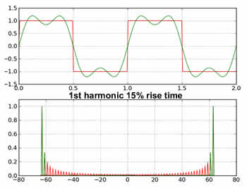
Anything over the sixth odd harmonic of this 1Mhz square wave will be at or greater than -3db attenuation due to the 15Mhz DSO Quad analog bandwidth, so a poor waveform is to be expected because of analog bandwidth limiting.
Another assertion claimed by you and others is that the Nyquist theory only requires 2x of the signal for a sampling rate. You failed to include the rest of that definition which says “a signal must be sampled at least twice as fast as it’s highest frequency component.” With the square wave this would require many odd order harmonics, so in your example above, to include the 13th odd harmonic, then you would require a sample rate of 54MSa/s to reproduce that 1Mhz square wave waveform accurately.
So even if the analog bandwidth could pass the 27Mhz harmonic (and it apparently can’t), then the sample rate would still be destroyed according to Nyquist while using a 36MSa/s sample rate.
If you fall back and say, OK, lets just use a signal generator that can only output the 5th odd harmonic and we know that we will have a slower rise time (less than 10%) source signal waveform because of this harmonic limit. The fifth order odd harmonic of 1Mhz is 11Mhz so the DSO Quad bandwidth can pass this harmonic. According to Nyquist, with fifth harmonic (11Mhz) being the highest frequency component, then 22MSa/s should accurately reproduce the poor quality input signal square wave, and the DSO Quad will reproduce that signal with its 36MSa/s capability.
So, in the end you will get a poor display of a 5th order odd harmonic limited signal input because of the signal itself, and you will also get a poor display of the perfect square wave input because of DSO Quad limitations as described above. As I had mentioned in my earlier posts, my poor quality function generator square wave signal looked pretty good on the DSO Quad because it didn’t have enough odd harmonics present to add the DSO artifacts when the DSO Quad capability is exceeded. When I said it looked reasonable, it did look nearly as good as the input signal with some limited sampling artifacts which resulted in narrowed alternations (10% narrowing at the alternation tops). In the same write up, I also stated that the DSO Quad signal generator signal looked terrible, and now this can be attributed to my other statement about the generator signal looking like a very good square wave up to 8Mhz (which means it has lots of odd harmonics present) on a more expensive o’scope.
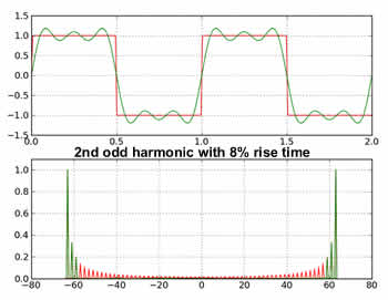
The attachments further clarify the above paragraph. You can see that the rise time for the 2nd odd harmonic waveform is about 6% (less than 10% rise time). So we will limit ourselves to the 2nd odd harmonic. This is 5 x 3.5Mhz = 17.5Mhz so it should get through the 15Mhz DSO Quad bandwidth with some amplitude fall off. I also mentioned in previous posts about some drooping of the tops and bottoms and this would indicate some kind of amplitude fall-off. According to Nyquist, the required sample rate would be 17.5Mhz x 2 = 35MSa/s. These numbers clearly show that I could in fact see the 10% rise time 3.5Mhz signal on the DSO Quad (with some amplitude distortion which I never measured).
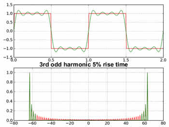
Now lets look at a 3.5Mhz perfect square wave by your definition (13th odd harmonic is present). 3.5Mhz x 27 = 94.5Mhz analog bandwidth requirement and will not do well with a 15Mhz DSO Quad bandwidth limit. For the same perfect square wave, the Nyquist sampling rate would be 94.5Mhz x 2 = 189MSa/s so that wont happen either. This is why you can’t look at the DSO Quad generator 2Mhz or 4Mhz square wave outputs on the DSO Quad display. It has nothing to do with the DSO Quad being defective, but is simply the result of the DSO signal sampling process while sampling a short rise time square wave.
In summary, in my first post in this thread I stated what I had observed but failed to talk about rise time as a factor for display results. Then Venarim in his first post stated that he didn’t believe that I saw that. And then the thread just rambled on. It is my intention that this post will set the record straight and also explain the reason for differing observations between Venarim and myself.
It also might be pointed out here in the bandwidth discussion, that if the DSO Quad design had a hardware trigger circuit (and it does not) then for repeating waveforms, the firmware could be designed for equivalent time sampling with a magnitude order increase in the maximum observable waveform frequency. That would have made a tremendous improvement to the DSO Quad, but that approach was never taken during the design leap from the Nano to the Quad.
My reference for this post is cbtricks.com/miscellaneous/t … mpling.pdf which is a Tektronics application note for Sampling Oscilloscopes.
 . But i can bet my mother (only speaking, don’t take me too serious
  ) that trigger is hardware (obviously is not an analog one, but digital). So QUAD can use equivalent time sampling for sure.
 , buffer sizes, sampling rates, time divs, ADCs, unity gain op-amps, low impedance signal path, parasitics and finally disembowelling
  my quad to fiddle with its innards.

 .
.