
Can’t reproduce that:

1.9 firmware crashes after calibration.

SPECT mode show blue screen and nothing on it…

In fact, screen is blue…
Strange vertical floating line…bug with SCAN mode…


Can’t check that now (working)
It’s just a test version.
You have to enable the FFT for the Spectrogram to work.
Issues/bugs list now available in the github site: https://github.com/pmos69/dso203_gcc/issues
…please contribute, either with reporting new issues or (preferably  ) with fixes.
I’ve been able to fix the analog outputs by changing this table
</s><i>
</i>A_tab A_Tab[15] ={ // analog waveform output driver table synthesis, based on the 72MHz frequency, per 36
//    STR     PSC     ARR
  {"! 1Hz !", 20-1,  50000-1},
  {"! 2Hz !", 20-1,  20000-1},
  {"! 5Hz !", 20-1,  10000-1},
  {" 10Hz ",  20-1,   5000-1},
  {" 20Hz ",  10-1,   2000-1},
  {" 50Hz ",  10-1,   1000-1},
  {"!100Hz!", 10-1,    500-1},
  {"!200Hz!", 10-1,    200-1},
  {"!500Hz!", 10-1,    100-1},
  {" 1KHz ",  10-1,     50-1},
  {" 2KHz ",  10-1,     20-1},
  {" 5KHz ",  10-1,     10-1},
  {"!10KHz!", 10-1,      5-1},
  {"!20KHz!", 10-1,      2-1},
  {"!40KHz!",  4-1,      5-1}};   // this value is wrong
<e>
However, some of the frequencies are not correct - but near and I do not know what to change to set it right. I am new to the STM32 and also the toolchain.
I do not have a reference to the SYS1.52 sources which seem to have the __Set(ANALOG_PSC) command. It is not in the SYS1.51 source. See this fragment
[code]/*******************************************************************************

Update_Output:

*******************************************************************************/

void Update_Output(void)

{
u8 att;
switch (_Kind) {
case SINE:
for(att=0; att <72; att++){
ATT_DATA[att]=(SIN_DATA[att]*Title[OUTPUT][OUTATT].Value)/100;}
DMA2_Channel4->CCR &= ~DMA_CCR1_EN;
***** __Set(ANALOG_PSC, A_Tab[_Frqn].PSC);
__Set(ANALOG_CNT, 72);
__Set(ANALOG_PTR, (u32)ATT_DATA);
DMA2_Channel4->CCR |= DMA_CCR1_EN;
__Set(ANALOG_ARR, A_Tab[_Frqn].ARR);
break;
[/code]
My setup has Chip SYS1.51, HW 2.60.
I think I’m using the “official” sys 1.51.
Can’t test it now, though.
Anyway, I don’t have a problem with the frequencies.
It’s, at least in marco’s sys.
See here: <LINK_TEXT text=“ftp://shodtech.net/DSO_Quad/marcosin_ch … ude/BIOS.h”>ftp://shodtech.net/DSO_Quad/marcosin_changes/source_V1.7/SYS1.6/include/BIOS.h</LINK_TEXT>
Yes I have the Bios.h which declares ANALOG_PSC. I am looking for the Sys package Bios.C which has the Set function. In the Sys1.51 files, there is no handler for the ANALOG_PSC case. Maybe that is causing the function to work on some DSO203? I want to backtrace and find the registers being manipulated so I can correct it.
Thanks for looking
This is from the file Bios.c from Sys1.51 here <LINK_TEXT text=“https://github.com/Seeed-Studio/DSOQuad … rce/BIOS.c”>https://github.com/Seeed-Studio/DSOQuad_SourceCode/blob/master/SYS_V1.50/source/BIOS.c</LINK_TEXT> No case for ANALOG_PSC as you can see.
[code]/*******************************************************************************

Set: 硬件控制设备设置

*******************************************************************************/

u32 Set(u8 Object, u32 Value)

{

switch (Object){

case CH_A_OFFSET: if(Value < 65536){

TIM5_ARR = 470; TIM5_CCR1 = 450 - Value; // Value = 0~200

} else {

TIM5_ARR = Value >>16; TIM5_CCR1 = Value & 0xFFFF;

} break;

case CH_B_OFFSET: if(Value < 65536){

TIM5_ARR = 470; TIM5_CCR2 = 450 - Value; // Value = 0~200

} else {

TIM5_ARR = Value >>16; TIM5_CCR2 = Value & 0xFFFF;

} break;

case BACKLIGHT: TIM8_CCR1 = Value; // Value = 0~100

break;

case BEEP_VOLUME: TIM8_CCR2 = 100 - Value/2; // Value = 0~50

break;

case BETTERY_DT: ADC3_CR2 |= (Value & 1)<<22; // Value = 1/0 ADC3_CR2 |=0x00400000;

break;

case ADC_MODE: if(Value == SEPARATE) FIFO_MODE_LOW();

else FIFO_MODE_HIGH(); break;

case FIFO_CLR: if(Value == W_PTR){FIFO_CLRW_HIGH(); FIFO_CLRW_LOW();}

if(Value == R_PTR){FIFO_CLRR_HIGH(); FIFO_CLRR_LOW();} break;

case T_BASE_PSC: TIM1_PSC = Value;

break;

case T_BASE_ARR: if(Value==0) {TIM1_CCER=0; RCC_CFGR=0x041D8402;} // MCO as SYSCLK

else if(Value==1) {TIM1_CCER=0; RCC_CFGR=0x071D8402;} // MCO as SYSCLK/2

else {RCC_CFGR=0x001D8402; TIM1_CCER=0x0003; // MCO as OC1

TIM1_ARR=Value; TIM1_CCR1=(Value+1)/2;}

break;

case CH_A_COUPLE: if(Value == AC ) AC_1(); else DC_1();

break;

case CH_B_COUPLE: if(Value == AC ) AC_2(); else DC_2();

break;

case CH_A_RANGE:

switch (Value){

case _50MV: Ax0_ON(); Ax1_ON(); Ax2_HIGH(); Ax5_HIGH();

break;

case _100MV: Ax0_ON(); Ax1_ON(); Ax2_LOW(); Ax5_HIGH();

break;

case _200MV: Ax0_ON(); Ax1_ON(); Ax2_HIGH(); Ax5_LOW();

break;

case _500MV: Ax0_ON(); Ax1_ON(); Ax2_LOW(); Ax5_LOW();

break;

case _1V: Ax0_OFF(); Ax1_OFF(); Ax2_HIGH(); Ax5_HIGH();

break;

case _2V: Ax0_OFF(); Ax1_OFF(); Ax2_LOW(); Ax5_HIGH();

break;

case _5V: Ax0_OFF(); Ax1_OFF(); Ax2_HIGH(); Ax5_LOW();

break;

case _10V: Ax0_OFF(); Ax1_OFF(); Ax2_LOW(); Ax5_LOW();

break;

case CH_B: Ax0_ON(); Ax1_OFF(); Ax2_LOW(); Ax5_LOW();

break;

} break;
case CH_B_RANGE:
switch (Value){
case _50MV: Bx0_ON(); Bx1_ON(); Bx2_HIGH(); Bx5_HIGH();
break;
case _100MV: Bx0_ON(); Bx1_ON(); Bx2_LOW(); Bx5_HIGH();
break;
case _200MV: Bx0_ON(); Bx1_ON(); Bx2_HIGH(); Bx5_LOW();
break;
case _500MV: Bx0_ON(); Bx1_ON(); Bx2_LOW(); Bx5_LOW();
break;
case _1V: Bx0_OFF(); Bx1_OFF(); Bx2_HIGH(); Bx5_HIGH();
break;
case _2V: Bx0_OFF(); Bx1_OFF(); Bx2_LOW(); Bx5_HIGH();
break;
case _5V: Bx0_OFF(); Bx1_OFF(); Bx2_HIGH(); Bx5_LOW();
break;
case _10V: Bx0_OFF(); Bx1_OFF(); Bx2_LOW(); Bx5_LOW();
break;
case CH_A: Bx0_ON(); Bx1_OFF(); Bx2_LOW(); Bx5_LOW();
break;
} break;
case ANALOG_ARR: GPIOB_CRL = 0x34BBB438; TIM4_CR1 = 0x0080; // SQR_OUT = Disnable
GPIOA_CRL = 0x111011BB; DAC_CR = 0x0001; // DAC = Ensable
TIM7_ARR = Value; TIM7_CR1 = 0x0085; break;// DAC_CLK = Enable
case ANALOG_PTR: DMA2_CMAR4 = Value;
break;
case ANALOG_CNT: DMA2_CNDTR4 = Value; // Fout = (Cnt*(ARR+1)/72)KHz
break;
case DIGTAL_PSC: TIM4_PSC = Value; GPIOA_CRL |= 0x40000; // DAC_OUT = Disnable
TIM7_CR1 = 0x0084; DAC_CR = 0; break; // DAC = Disnable
case DIGTAL_ARR: TIM4_ARR = Value;
break;
case DIGTAL_CCR: GPIOB_CRL &= 0xF0FFFFFF; GPIOB_CRL |= 0x0B000000; // PORT_SQR = Enable
TIM4_CCR1 = Value; TIM4_CR1 = 0x0081; break; // SQR_OUT = Enable
case KEY_IF_RST: TIM3_SR = 0; //Clear TIM3 interrupt flag
break;
case STANDBY: if(Value == 1) { STB_EN();} else { STB_DN();}
break;
case FPGA_RST: GPIOB_CRH &= 0xF0FFFFFF; GPIOB_CRH |= 0x01000000; // 设PB14为输出状态
SPI_CRST_LOW(); Delayms(1); // SPI_CRST_LOW 1mS
SPI_SS_HIGH(); Delayms(1); // SPI_SS_HIGH 1mS
SPI_SS_LOW(); Delayms(1); // SPI_SS_LOW 1mS
SPI_CRST_HIGH(); Delayms(2); // SPI_CRST_HIGH 2mS
GPIOB_CRH &= 0xF0FFFFFF; GPIOB_CRH |= 0x08000000; break; // 设PB14为输入状态
case TRIGG_MODE: Set_Param(Object, Value);
break;
case V_THRESHOLD: Set_Param(Object, Value);
break;
case T_THRESHOLD: Set_Param(Object, Value & 0xFF);
Set_Param(Object +1, Value >> 8); break;
case ADC_CTRL: Set_Param(Object, Value);
break;
case A_POSITION: Set_Param(Object, Value);
break;
case B_POSITION: Set_Param(Object, Value);
break;
case REG_ADDR: Set_Param(Object, Value);
break;
}
return 0;
}[/code]
It’s in the same place Jerson: <LINK_TEXT text=“ftp://shodtech.net/DSO_Quad/marcosin_ch … rce/BIOS.c”>ftp://shodtech.net/DSO_Quad/marcosin_changes/source_V1.7/SYS1.6/source/BIOS.c</LINK_TEXT>
Just checked, and I’m actually using Marco’s SYS 1.50 1.6
Yes to run the signal generator in right mode, it’s necessary the sys 1.50 1.6 i don’t remember what i have changed but i remember that i’ve modified something.
I’ve just changed the readme.txt to reflect this.
Can’t reproduce this…
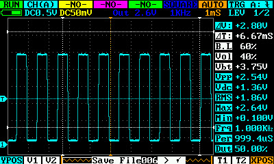
Pmos69, i have make some modify to Your old 1.18 version, this is a screenshoot.
-The FFT function and FFT source can be selected from the track4 menù, it’s possible select the ch A or ch B. They are displayed as track4 math results.
-I’ve changed some colors
-I’ve changed the FFT meter positions, the max meter moves along the peak position
There are stupid modify, but if you think that are interesting, i can send to You the code to integrate it in the next version. Maybe you first do it without my code!!! hehehe.
Thanks Marco, that looks much better. Great.
I didn’t do much more, because I’m leaving for Zurich tomorrow and I’ll be away for a week because of work.
But send the code and I’ll try to do it as soon as I can. (I’ll bring the dso with me )
All the best,
Pedro
Hello Pedro
The sys was a problem. Updating from Marcos binary corrected the problem.
Now, my setup has
HW 2.60
SYS 1.50 SmTech 1.6
Thanks very much
Regards
Jerson
Here the modified files.
In the sources i have deleted the “interlace mode” because it’s never used in the software. In this mode we have more free memory.
Thanks
Marco
Here are the code modifications necessary to fix the trigger (they’re all on Process.c):
At the start of the file, declare:
</s>u8 HoldOnNext=0;<e>
In Synchro() change
[code]  if((_Status == RUN)&&(__Get(FIFO_FULL)!=0))

{    // FIFO is full

__Set(FIFO_CLR, W_PTR);                       // FIFO write pointer reset

Wait_Cnt = Wait[_T_base];

JumpCnt =0;
if(_Mode == SGL)
{
_Status = HOLD; // one finished, enter the pause
_State.Flag |= UPDAT;
}
}[/code]
to
[code]  if(HoldOnNext==1) {

_State.Value = HOLD;                             // one finished, enter the pause

_State.Flag |= UPDAT;

HoldOnNext=0;

return;

}
if((_Status == RUN)&&(__Get(FIFO_FULL)!=0)){ // FIFO is full
if((_Mode != SGL)) {
__Set(FIFO_CLR, W_PTR); // FIFO write pointer reset
}
Wait_Cnt = Wait[_T_base];
JumpCnt =0;
if(_Mode == SGL){
HoldOnNext=1;
}
}
[/code]
That should be all 
Thanks!