This is the tobey statement that I was referring to. tobey does have more than one agenda and I don’t quite understand some of it, but I was referring to the fast scan as being less than optimum for typical use of that scan feature. If the Scan mode honored the Fast option selection, then the user can decide how to use Scan. It is very difficult to communicate successfully in this one-way forum medium (without immediate feed-back to confirm understanding) and that is why these posts can get frustrating at times for all of us.
That statement caught me off guard. Now I think I understand what you were considering and that I was missing. It sounds like you are saying that in Fast Post, a portion of the left half of the display could be blank and I hadn’t considered that. I guess we have come to the cross-roads of user capability versus complex functionality. I would quickly realize that when Fast Post leaves the left side of the screen blank, then I would just use the trigger position to slide the whole display to the left as required. A user with less knowledge base might consider the blank screen area as a problem or bug. It sounds like you are considering sliding the trigger position to the left of the screen to protect the less qualified user and that certainly has it merit. Explaining this situation in the User Guide would be another option.
Maybe I can improve my communication here. My examples referred to a common time domain which has the T/Div the same so I don’t see a need to make the time bases independent. I may have indicated that in an earlier post but have since decided that it is unnecessary complexity.
As far as default program behavior is concerned we could never change the REF waveform before, so keeping the V/Div fixed to the loaded XML parameter is not a change in behavior of the Ref waveform. The Ref waveform following the T/Div would in fact be an advantage such that both waveforms could be stretched simultaneously for closer examination for differences.
As you have indicated, cursors for the Ref waveform would not be necessary for a common T/Div.
Vertical position offset is most useful whereas horizontal offset provides little if any advantage.
In summary, my suggestion is that we only need 3 changes; to preserve the XML V/Div of the Ref waveform to correct for the comparison of large signals and small signals, to keep the Ref waveform vertical offset disconnected from the primary waveform vertical offset so that the two waveforms can be separated in the vertical plane, and to isolate the Ref waveform from Gnd Pos changes to ensure that vertical separation can be maintained.
If you’re able to conclusively describe the difference between a good and bad waveform, there is a fair chance that fault finding/diagnostics can be automated. Perhaps you should explain what this is really about and include accurate examples of waveforms (good and bad).
If we leave trigger position centered then 50% of the screen will always be blank when in fast mode and using post priority. Still your idea has some merit if we stop acquisitions and use pan/zoom to look closer at the waveform. Typical usage for post priority however is likely to be digital waveforms where the user is attempting to decipher some communication protocol. In this context, fast mode is less relevant. Fast mode is appropriate when we need a “high definition” acquisition of a single complex signal.
If we agree that comparing for equality is the primary use for a reference wave then any feature that compromise this should not be default. In this context I think the current behavior is appropriate and so this implies additional controls are needed for the added features.
Again, I appreciate your input so will keep this in mind for future updates.
That is one application, another application of Fast Post is when looking at a complex pulse signal and the interest lies in any ringing, noise, or slope deterioration of the pulse edges. For example, the fuel injector current signal rise time can be expanded to see when the actual injector pintle opens up (due to counter EMF caused by the pintle motion). When the injector pintle closes a similar glitch can be seen on the waveform. In this application, you would want a Fast Post so the waveform can be expanded horizontally as much as possible (with fast refresh rate for real-time viewing) and use the Trig Pos to place all of the expanded pulse on the screen in real-time.
In the current firmware version I can slide the Trig Pos to the left and leave it there for real-time waveform viewing without having to stop acquisitions. Now I can view the expanded Fast Post waveform in great detail at real-time fast update rates.
Although I mentioned the automotive application, there are many other uses where Fast Post would enable more accurate pulse width adjustments and also provide for better viewing of complex pulse irregularities in real-time with a fast refresh rate.
For off-line viewing of the captured XML files, the Fast Post XML file will not waste buffer space (sequence numbers) on information that is not desired. Instead, twice as much desired information post trigger will be available for examination.
Hope this serves to demonstrate why I think the Fast Post feature is important.
As you mentioned in previous posts, for Fast Post, the firmware could pre-position the Trig Pos near the left side of the display and then the user could fine adjust as required.
something else that would be an awsome feature is positive and negative duty cycle measurement in the same way that the new awsome pulsewidth feature is set up by using trigger to select pos or neg …currently we only have positive…i would use this feature many times over and the same with other auto guys… and example would be you read pwm commands with positive duty and pwm actuators with negative duty… same with crank sensor and injector measurements so this feature and fast post buffer will make it perfect from a auto mechanics point of veiw
Yea I second that request …that would be a nice competetive edge feature over other dso makers also…You took the words right out of my mouth on this one Brandon…
Thanks to lygra for pointing out some good applications for fast mode sampling.
Some may argue that we should honor the definition of duty cycle (positive ratio) as long as this term is used and others may claim this will help sharpen our basic algebra skills (subtracting a value from 100). From a firmware/usage perspective however I don’t see any reason why we could not adopt the pulse width convention.
We need the three digits of precision as otherwise a value like 14.4V would become 14V. For a lead acid charge circuit (and I trust a number of other applications) this difference is significant. There is also the possibility to display all measurements simultaneously for when numeric values are more important than the waveform.
Still I realize that sometimes two is better than one. What would be your favorite two measurements and is there a specific application you had in mind?
In the current firmware we have 4 cursors (two for time and two for voltage) that can be used for measurements as you indicate. When moving cursors, the cursor absolute value is displayed in the context sensitive information field (lower right) and deltas in dedicated fields.
do You think we could have 2 MeasureValues on the Top Bar ?
another idea: what about the Bottom Bar?
There are “^V” and “^T” fields of Cursor-Values (often unused)
left and right Measurement-Values can be displayed there,
this gives a total of 3 MeasurementValues:
in TopBar, selected with “OK” (like it is now)
left in BottomBar = left arrow (former ^V)
right in BottomBar = right arrow (former ^T)
after startup,
“Vpp” and “Vavg” is displayed instead of “^V” and “^T”
user can select any value there…
But if the user selects any Cursor, a flag is set,
so “^V” or/and “^T” is shown there from now on,
until the user selects a Measurement-Value again.
Do You like it ?
I would like to see a lot of Measurement, it is pure fun
Hi Ben,
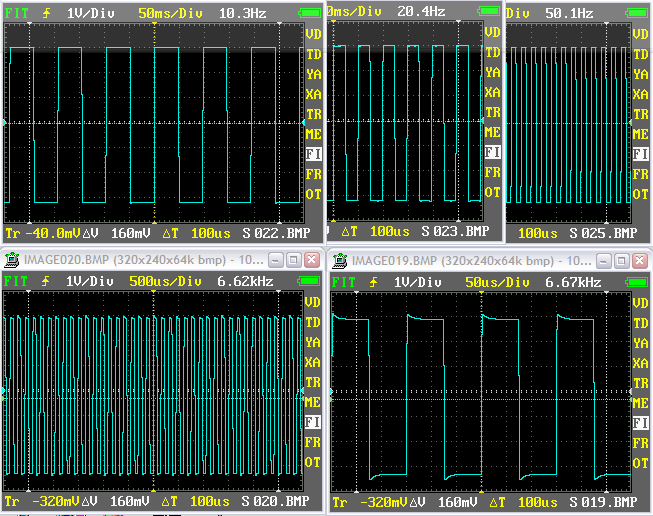
would You please have a look to the FIT algorithm :
Starting with 1Hz it stays too long on 50ms showing too much waves,
it displays 20 or more waves until 16.6kHZ
where it suddenly jumps from 200us to 20us/Div giving 4 waves.
Then, if You go down to 6.6kHz 50us it jumps to 500us again.
Another fine upgrade to V3.61. I am always impressed with the fact that there are seldom bugs in your updates. We all appreciate your professionalism. The way you implemented fast was very well thought out. Your Load Factory option was a nice touch in keeping with the expanded functionality settings of the Nano.
Hello. I’m new here. Ordered a nano v2 and sent one to my friend in Alaska. Highly recommended by Dr.Brandon of the Autonerds. I must say he is a very special person that bends over backwards to help fellow mechanics in very far away places. I look forward to using my nano and learning from you guys here. I have a pico 4 channel scope I purchased from Tom Roberts and enjoy using it. I’m not smart enough on dso’s to be making any recommendations so I will just be a lurker. Thanks. Jake Payne, Laurens,SC.
BenF - After using the Factory Default profile, I would suggest that the Factory Profile settings include Trig Sens = 0mV instead of the current value of 320mV. Many o’scopes and users are not familiar with the Trig Sens concept and the Factory value of 320mV could cause unexpected trigger issues with small signal triggering conditions. I don’t understand why the Factory Gnd Pos is set to -60 instead of zero but I guess you have a reason.
The main objective with the new reset option was to provide a means to initialize the DSO to some known working defaults. This allows for a common starting point when assisting other users. Your comments on choice of values make sense and I will review them next time around.
As for trigger sensitivity (the concept is inherited from the 2.5e firmware), I’ve been thinking about removing it altogether. This option would make sense for say a pulse trigger (sensitivity in the time domain), but not really needed for edge triggers. Perhaps someone would like to challenge my “ignorance” in this respect and point to some relevant scenario where this feature might be handy also with edge triggers?